Q-See QT528 User Manual
User manual, Qt528, Model
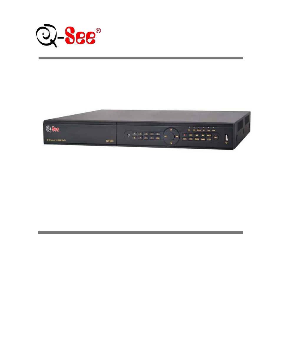
Table of contents
Document Outline
- 1. INTRODUCTION
- 2. GETTING STARTED
- 2.1 Connecting to a monitor or TV
- 2.2 Installing Hard Drive
- Step1: Unscrew and Open the top cover
- Step2: Connect the power and data cables. Place the HDD onto the bottom case as below.
- Step3: Screw the HDD as below.
- Note: For the convenience to install, please connect the power and data cables firstly, and then screw to fix.
- Note: For easier installation, please connect the power and data cables first, and then screw the HDD to base.
- 2.2.1 Install DVD Writer
- 2.3 Front Panel Descriptions
- 2.4 Rear Panel Layout
- 2.5 Remote Control
- Uses two AAA size batteries, to install batteries:
- Step1: Open the battery cover of the Remote Control
- Step2: Insert batteries. Position the poles (+ and -) correctly
- Step3: Replace the battery cover
- 1. Check batteries poles
- 2. Check the remaining charge in the batteries
- 3. Check to see if IR controller sensor on DVR is blocked
- If it still doesn't work, contact the Q-See customer service dept to replace the remote control.
- The interface of remote controller is shown in Fig2.6 Remote Controller.
- The device ID of the DVR is 0. When using remote control to control a single DVR, it’s not necessarily to reset the device ID; when controlling multiple DVR with remote controller, please refer to below steps:
- Step1: Activate remote control to control DVR: enable DVR: Point the IR sensor of the remote control at the IR receiver that on the front panel of the DVR, press the number key 8 twice, then input device ID (Range from: 0-65535; the default device ID is 0.) with another digital number: 0-9, after that, press ENTER button to confirm.
- Step2: User can check the device ID by entering into System configuration(Basic configuration(device ID. User also can set other DVR with the same device ID. For easier operation, we don’t recommend user set the device ID too long.
- Step3: To cancel a device ID: Point the IR sensor of the remote control at the IR receiver that is on the front panel, press the number key 8 twice, then input the device ID that needs to be cancelled, press ENTER button to confirm. After that, the DVR will not be controlled by remote control.
- 2 6 Control with Mouse
- Notice: Mouse is the default tool for all the operations below unless otherwise noted.3. BASIC FUNCTION
- 3.1 Power On/Off
- Before you power on the unit, please make sure all the connections are good.
- 3.1.1 Power On
- Step 1: Connect the power supply; switch on the power button near the power port on the rear panel
- Step 2: The firmware will be loaded, and the power indicator will display blue
- Step 3: At start up, a WIZZARD dialogue box will pop-up (refer to picture below) displaying time zone and time setup information.
- After the device powers on, if there is no menu or only displays live image, user can hold down ESC button to switch.
- 3.1.2 Power Off
- User can power off the device by using remote control, keyboard or mouse.
- By Remote Control:
- Step 1: Press Power button, the Shut down window will appear, click OK, the unit will power off after firmware is shut down.
- Step 2: Disconnect the power.
- By Keyboard and Mouse:
- Step 1: Enter into Menu, then select “System Shut Down” icon, the Shut down window will appear
- Step 2: Click OK, the unit will power off after firmware is shut down.
- Step 3: Disconnect the power.
- 3.2 Login
- 3.3 Live Preview
- 3.1 Power On/Off
- 4. MAIN MENU SETUP GUIDE
- Click right mouse or press ESC button on the front panel, the control bar will display on the bottom of the screen, refer to Fig 4-1:
- Click icon beside the screen display mode, a channel select dialog will appear as below:
- Take 8-channel DVR for example: user can tick off 8 channels form 1-ch to 8-ch at random to display the live pictures. Then click button to confirm the setting.
- Click icon, user can zoom in the live and playback images. When single image display, user can select zoom in area by dragging mouse.
- Click the Menu button, the interface will pop-up as shown in Fig 4-2; press MENU button on the front panel or remote control will also display the main interface.
- 4.1 Basic Configuration
- Basic configuration includes three sub menus: system, date& time and DST.
- 4.1.1 Setup
- Step1: Enter into Setup configuration(basic configuration(setup; refer to Fig 4-3:
- Step2: In this interface user can setup the device name, device ID, video format, max network users, VGA resolution and language. The explanations for each display are shown below:
- Device name: the name of the device. It will display on the client end or CMS and help user to recognize the device remotely.
- Video format: two modes: PAL and NTSC. User can select the video format according to that of camera, in USA and Canada we use NTSC cameras.
- Password Check: if you enable this option, user needs to input user name and password to do corresponding operations in system configuration.
- Show time: display time in live view.
- Show wizard: check this item, an opening wizard will display with time zone and time setup information
- Max network users: set the maximum number of network connections
- VGA resolution: the resolution of live display interface, options are: VGA800*600, VGA1024*768, VGA1280*1024 and CVBS
- Note: Switching between VGA and CVBS will change the menu output mode, please connect to relevant monitor, VGA for VGA monitor, CVBS for TV or monitor that is connected using BNC adapter.
- Language: setup the menu language.
- Note: after changing the language and video output, the device needs to restart.
- 4.1.2 Time & Date
- Step 1: Enter into system configuration(basic configuration(time & date; refer to Fig 4-4:
- Step 2: Set the date format, time format, time zone in this interface; Checkmark “sync time with NTP server” to refresh NTP server date; user also can adjust system date manually
- Step 3: Click “default” button to restore default settings; click “apply” button to save the settings; click “exit” button to exit current interface.
- 4.1.3 DST
- 4.2 Live Configuration
- Live configuration includes four submenus: live, host monitor, SPOT and mask.
- 4.2.1 Live
- In this interface, user can setup camera names, adjust colors: brightness, hue, saturation and contrast.
- Step 1: Enter into system configuration(live configuration(live; refer to Fig 4-6:
- Step 2: Checkmark camera name; click “setting” button, a window will pop-up shown as Fig 4-7:
- Step 3: In this interface, user can adjust brightness, hue, saturation and contrast in live view; click “default” button to restore default settings, click “OK” button to save the settings.
- Step 4: User can setup all channels with same parameters, checkmark “all”, then do relevant setup.
- Step 5: Click “default” button to restore default settings; click “apply” button to save the settings; click “exit” button to exit current interface.
- 4.2.2 Host Monitor
- Step 1: Enter into system configuration(live configuration(host monitor; refer to Fig 4-8:
- Step 2: Select split mode: 1Ч1, 2Ч2, 2Ч3, 3Ч3, and channel
- Step 3: Dwell time: the time interval for a certain picture display before switching to next picture display
- Step 4: Select the split mode, then setup current picture group. Click button to setup the previous channel groups of pictures, click button to set latter channel groups of pictures.
- Step 5: Click “default” button to restore default settings; click “apply” button to save the settings; click “exit” button to exit current interface.
- NOTE: If you have dual monitors Host monitor needs to be main monitor.
- 4.2.3 SPOT
- Step 1: Enter into system configuration(live configuration(SPOT; refer to Fig 4-9:
- Step 2: Select split mode: 1×1 and channel
- Step 3: Dwell time: the time interval for a certain picture display before switching to the next picture display.
- Step 4: Select the split mode, then setup current picture group. Click button to setup the previous channel groups of pictures, click button to set the latter channel groups of pictures.
- Step 5: Click “default” button to restore default setting; click “apply” button to save the setting; click “exit” button to exit current interface.
- To activate this setting, go to the main camera screen and click on the Dwell icon (Fig 4-1). This will make the camera rotate based on the setting in Main Monitor.
- 4.2.4 Mask
- 4.3 Record Configuration
- Record configuration includes five sub menus: enable, record bit rate, time, recycle record and stamp.
- 4.3.1 Enable
- Step 1: Enter into system configuration(record configuration(enable; refer to Fig 4-11:
- Step 2: Checkmark record, audio and record time
- Step 3: User can setup all channels with same parameters, checkmark “all”, then do relevant setup.
- Step 4: Click “default” button to restore default setting; click “apply” button to save the setting; click “exit” button to exit current interface.
- Definitions and descriptions of Record:
- Parameter
- Meaning
- Record
- Switch Record on or off
- Audio
- Enable live audio recording
- Redundancy
- 4.3.2 Record stream
- Step 1: Enter into system configuration(record configuration(record bit rate; refer to Fig 4-12:
- Step 2: Setup rate, resolution, quality, encode and max bit stream
- Step 3: User can setup all channels with same parameters, checkmark “All”, then to do relevant setup.
- Step 4: Click “default” button to restore default setting; click “apply” button to save the setting; click “exit” button to exit current interface.
- Note: if you set a value that is higher than maximum supported by the device, the value will be adjusted automatically.
- Definitions and descriptions of Record stream:
- Parameter
- Definition
- FPS
- Range from 1-30 (NTSC) 1-25 (PAL)
- Rate
- Range from: 1-30(NTSC)1-25(PAL)
- Resolution
- CIF or D1 Each camera can use either resolution option
- Quality
- The quality of recorded images. The higher the value, the clearer the recorded image is. Six options: lowest, lower, low, medium, higher and highest.
- Encode
- VBR and CBR
- Max bit stream
- Range from: 64 Kbps、128 Kbps、256 Kbps、512 Kbps、768 Kbps、1Mbps、2 Mbps
- 4.3.3 Time
- Step 1: Enter into system configuration(record configuration( time; refer to Fig 4-13:
- Fig 4-13 Record Configuration-Time
- Pre-alarm record time: set the record time before event happen i.e. record time before motion detection or sensor alarm is triggered.
- Post-alarm record: set the post recording time after the alarm is finished, five options: 10s, 15s, 20s, 30s and 60seconds.
- Expire time: the hold time of saved records. When the set date has passed, the record files will be deleted automatically.
- Step 2: User can setup all channels with same parameters, checkmark “all”, then to do relevant setup.
- Step 3: Click “default” button to restore default setting; click “apply” button to save the setting; click “exit” button to exit current interface.
- 4.3.4 Recycle Record
- Step 1: Enter into system configuration(record configuration(recycle record;
- Step 2: Checkmark recycle record, the recycle record function will be enabled, it will overwrite the earlier recorded files and keep recoding when HDD is full; if not enables the DVR will stop recording when HDD is full.
- Step 3: Click “default” button to restore default setting; click “apply” button to save the setting; click “exit” button to exit current interface.
- 4.3.5 Stamp
- Stamp:User can display the channel name and time stamp on video.
- Step 1: Enter into system configuration( record configuration( stamp; refer to Fig 4-14:
- Step 2: Checkmark camera name, time stamp; click Set button, user can use cursor to drag the camera name and time stamp to random positions, refer to below Figures:
- Step 3: User can setup all channels with same parameters, checkmark “all”, then to do relevant setup.
- Step 4: Click “default” button to restore default setting; click “apply” button to save the setting; click “exit” button to exit current interface.
- 4.4 Schedule Configuration
- 4.5 Alarm Configuration
- 4.6 Network Configuration
- 4.6.1 Network
- 4.6.2 Sub Stream
- Parameter
- Meaning
- FPS
- Range from: 1-30
- Resolution
- Supports CIF and D1
- Quality
- The quality of the video image. The higher the value is, the clearer the recorded image, and the more hard drive space the recordings take up. Six options: lowest, lower, low, medium, higher and highest.
- Encode
- VBR and CBR
- Max bit rate
- Range from: 64 Kbps, 128 Kbps, 256 Kbps, 512 Kbps, 768 Kbps, 1Mbps, 2 Mbps
- 4.6.3 Email
- 4.6.4Other settings
- 4.7 User Management Configuration
- 4.8 P.T.Z configuration
- 4.9 Advanced
- 5. RECORD, SEARCH, PLAYBACK AND BACKUP
- 6. DVR MANAGEMENT
- 7. REMOTE SURVEILLANCE
- 7.1 Network Access
- 7.2 Setting Up Remote Access
- 7.3 Port Forwarding
- Notice: If you still have problems connecting remotely: Anti-virus programs could also block the ActiveX control, if you still have a problem try closing them. Other plug-ins could also block it. Close firewalls in Windows and in the router if applicable. If you run Windows Vista or Windows 7, you will need to disable User Account (UAC).Follow this link for instructions:
- http://www.howtogeek.com/howto/windows-vista/disable-user-account-control-uac-the-easy-way-on-windows-vista/
- 7.5 Using the Remote Access Software
- 1. Click “Snap” icon, select the number of pictures, refer to Fig 7-23:
- 2. User can take multiple pictures , select the picture number from snap count pull down list box, such as 3, checkmark “Title” and “Time”, it will show capture title and time on the snap pictures simultaneously. Refer to Fig 7-24:
- 3. Click “Browse” to set saving path; Click “Save” to save pictures to HDD on the computer; click Exit button to exit current interface.
- 7.6 Remote Playback and Backup
- 7.7 Remote System Configuration
- 8. MOBILE SURVEILLANCE
- 8.1 Phones with Windows Mobile Pro
- Step 1: First you will need to activate network access on the mobile phone and then run “Internet Explorer”. Input the DVR’s IP address and then setup the connection as shown below:
- Step 2:Click on the software name. A dialog box pops up:
- Step 3:Click “Yes” to start downloading and installing:
- Step 4:PCam will open automatically once the install process is complete.
- Step 5:Input the DVR’s address, ID and password respectively in the columns of “Server”, “User” and “Password”, and click “Go” to log on the DVR. It will show the picture if accessed successfully.
- Step 6:Camera 1 is the default channel after login. Change the channel in the drop down menu of “Channel”:
- 8.2 Phones with Symbian
- Step 1:First enable the network access on the mobile phone. Then run Web browser.
- Step 2:Input the DVR’s IP address in a new-built bookmark. Click this bookmark to connect to the DVR.
- Step 3:A welcome window will pop up and requires a package. Click the software name to download
- Step 4:A security window will pop up after downloading and ask if you want to install the package. Click YES to install.
- Step 5:A Scam shortcut icon appears on the system menu after finished.
- Step 6:Run Scam program. It will display a function interface.
- Step 7:Click System setting--->Login Setting to enter login interface.
- Step 8:Input the DVR’s address, ID and password respectively. Then save.
- Step 9:Enter Live View, it will connect to the server and display pictures.
- Step 10:In Live View, users can do snapshot, change channels and control PTZ cameras.
- 8.3 For iPhone Mobile Clients
- 8.4 For Android Mobile Clients
- 8.5 For Blackberry Mobile Clients
- 8.1 Phones with Windows Mobile Pro
- Server list
- Software configuration
- Information view
- 9. PRODUCT SPECIFICATIONS