Chapter 2 installation instructions – Foxconn 6627MA-RS2H User Manual
Page 22
Chapter 2 Installation Instructions
15
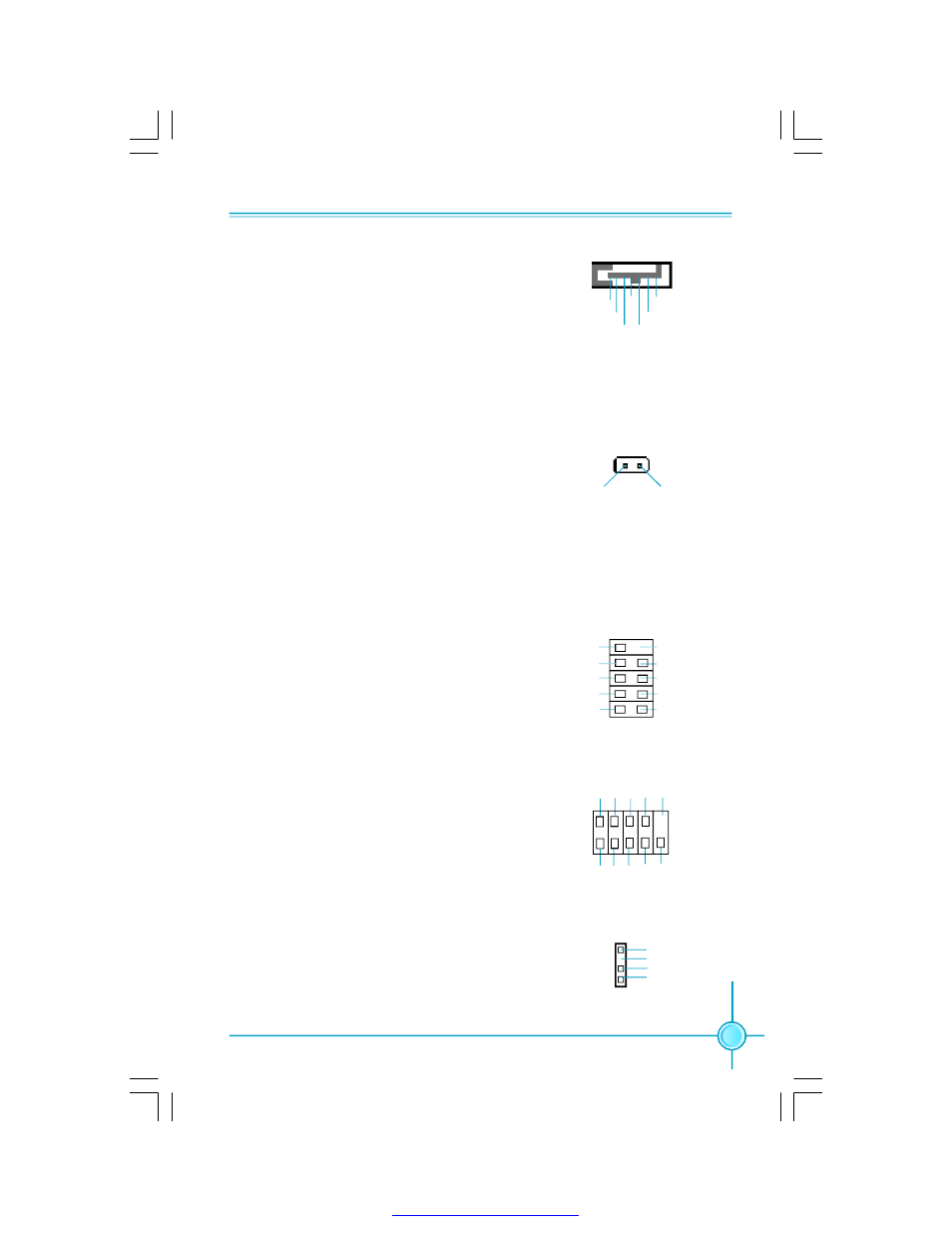
Serial ATA Connectors: SATA_1, SATA_2,
The Serial ATA connectors are used to connect
the Serial ATA device to the motherboard. These
connectors support the thin Serial ATA cables for
primary storage devices. The current Serial ATA
interface allows up to 150MB/s data transfer rate.
1
SATA_1/2
GND
GND
GND
RX +
RX-
TX -
T X +
Chassis Intruder Connector: INTR
The connector connects to the chassis security
switch on the case. The system can detect the
c h assis in tru sio n th rou g h th e statu s o f th is
connector. If the connector has been closed once,
the system will send a message. To utilize this
function, set
“Case Open Warning” to “Enabled”
in the
“PC Health Status” section of the CMOS
Setup. Save and exit, then boot the operating sys-
tem once to make sure this function takes effect.
1 INTRUDERJ
INTR
2 GND
USB Headers: F_USB1, F_USB2
Besides four USB ports on the rear panel, the
series of motherboards also have two 10-pin
headers on board which may connect to front
panel USB cable (optional) to provide additional
four USB ports.
F_USB 1/2
1
5 V_ DUAL
D-
D+
D-
GND
GND
D+
NC
E mpty
5 V_ DUAL
Additional COM Connector: COM2 (optional)
This motherboard provides an additional serial
COM header for your machine.
Connect one side of a switching c able to the
header, then attach the serial COM device to the
other side of the cable.
Speaker Connector: SPEAKER (optional)
The sp eak er c o n n ec to r is u sed to c o n n ec t
speaker of the chassis.
SPEAKER
1
SPKJ
NC
SPKJ
E mpt y
COM2
SOUT
GND
RLSD
RI#
DTR#
DSR#
SIN
9
10
1
2
CTS#
RTS#
Empty
PDF 文件使用 "pdfFactory" 试用版本创建