Safety 2, In stal la tion 2, Re ceiving and in spec tion 2 – Deltech Fitness PYRAMID 8000 User Manual
Page 8: Pu ri fier data plate part no. 44de23a 2, Safety installation, Receiving and inspection, Danger label: grossly contaminated air, Part no. 56de152a purifier data plate, Part no. 44de23a, Purification process
and outlet piping must be as large as the connections
or larger. Piping that is smaller than the purifier con-
nections will increase pressure drop and reduce breath-
ing air flow.
Install a pressure gauge at the purifier inlet to indicate
purifier operating pressure. Install shutoff valves be-
fore and after the purifier. Install a depressurization
valve between the purifier and the outlet shutoff valve
to vent internal pressure so that maintenance can be
performed safely.
If bypass piping is installed around the purifier, a sec-
ond purifier must be installed in the bypass line.
WARNING
Without a second purifier in the bypass line
air in the bypass will not be purified.
After piping has been installed, gradually pressurize
the system. Check and correct all connections for leaks
before operating the purifier.
Drain Piping
Two electronic drain valves automatically discharge
accumulated liquids from the coalescing filter. Drain
lines are located inside the cabinet for shipping. Uncoil
both lines; run the lines to a collection tank or an envi-
ronmentally approved disposal system. Secure the free
ends to prevent the lines from whipping when the
drains discharge.
If longer drain lines are required,
5
16
² O.D. flexible
plastic tubing up to ten feet long may be used. For dis-
charge lines longer than ten feet use
3
4
² pipe or larger
as required to avoid back pressure in the drain lines.
Electrical Connections
Electrical service access is clearly marked on the puri-
fier. Connect a fused AC power supply to the power
connections in the electrical enclosure. Run the wire
through the conduit connection. See Table III and Fig-
ures 4a, 4b and 4c for electrical system details.
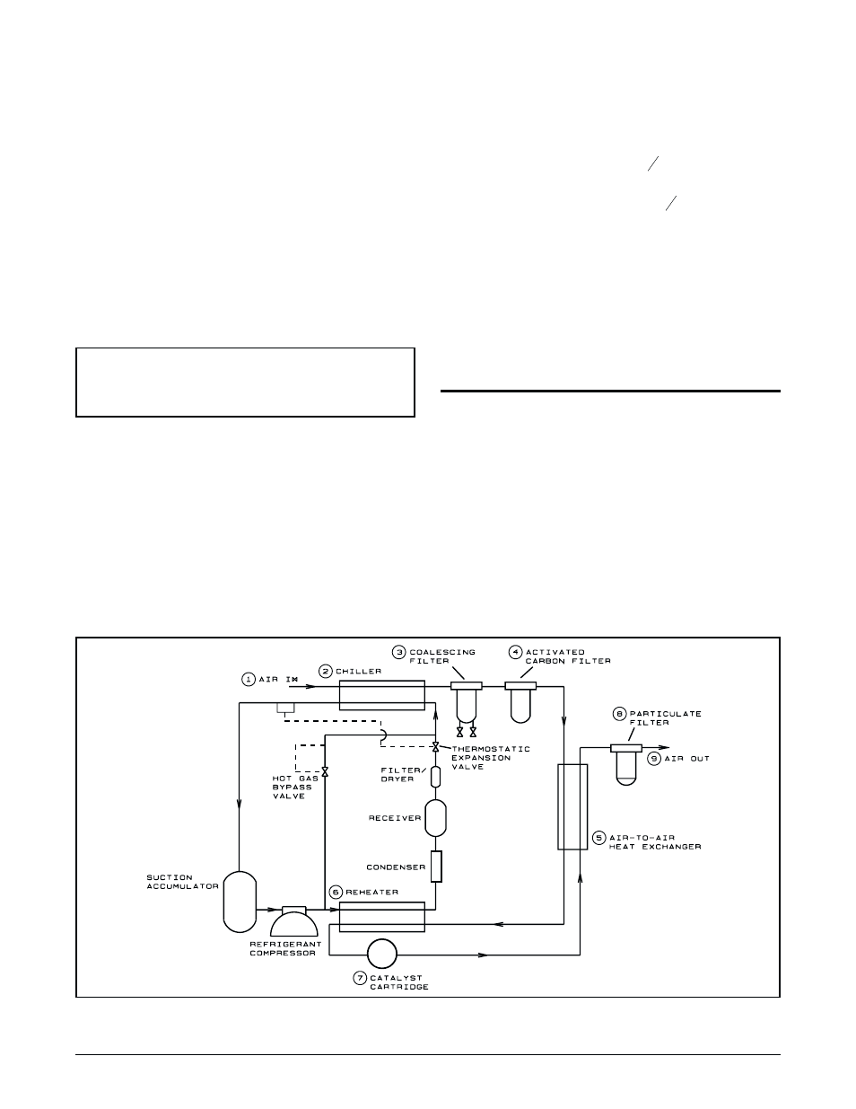
PURIFICATION PROCESS
Figure 1 illustrates the major components of the puri-
fier air and refrigerant circuits. These circuits work to-
gether to purify inlet air as follows:
¬ Air enters the purifier from the compressor/after-
cooler.
The chiller (air-to-refrigerant heat exchanger) cools
the inlet air and condenses entrained hydrocarbons and
water vapor.
4
Pyramid 8000
®
Series Purifiers (Bulletin 289)
Figure 1. Air and Refrigerant Flow Diagram