Fluke Biomedical 10100AT User Manual
Page 75
Appendix
Energy Correction Factors
C
C-7
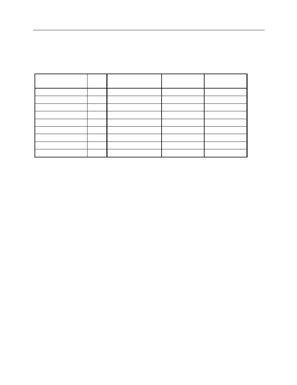
C.6.2 Diagnostic - Attenuated Beam (Behind the phantom)
The energy correction factors for the 96035B in the attenuated diagnostic beam are determined using the
PTB defined DN series of beam qualities given below in Table C-2.
Table C-2. Specifications for PTB Defined Attenuated Beam Qualities
PTB Denomination
kVp
Added Filtration
in mm Al
First HVL
in mm Al
First HVL
in mm Cu
DN40 40
6.5 2.2
0.07
DN50 50
12.5 3.4
0.123
DN60 60
18.5 5.0
0.207
DN70 70
23.5 6.2
0.289
DN80 80
29.5 7.8
0.403
DN90 90
32.5 9.0
0.501
DN100 100
36.5 10.1
0.609
DN120 120
42.5 12.0
0.839
DN150 150
52.5 14.1
1.245
Typical correction factor curves are obtained by dividing the calibration factor at each beam quality by the
calibration factor at a reference point and plotting the result versus first HVL.
The typical correction factor curve for the attenuated beam is normalized to DH70 in Figure C-5. DH70 is
a new PTB beam quality with an HVL of 6.77, which falls between DN70 and DN80. Since the response
of the chamber at H60 is virtually identical to the response at DN70, this curve is also considered
normalized to H60. Users receiving the standard calibration must request a calibration factor at either
H60 or DH70 to use the correction factors in this curve.
All 96035B ion chambers must have an actual correction factor within ± 1.5% of the value shown in the
curve at any point.
The numerical value shown beside each point is the kVp value of that point in the DN series of beam
qualities. Users making measurements in an attenuated beam with characteristics similar to the PTB DN
series may use these values to easily obtain the appropriate correction factor. For a more precise
correction factor value, or when making measurements in an attenuated beam not similar to a DN series
point, the user may measure the actual first HVL and locate the proper correction value on the curve.