10 using the ion chamber cable stem, 11 measurement considerations – Fluke Biomedical 10100AT User Manual
Page 40
10100AT
Operators Manual
2-22
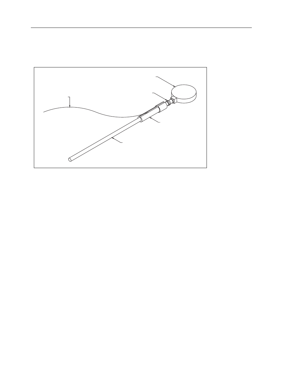
2.10 Using the Ion Chamber Cable Stem
To accurately remote position the ion chamber in an image intensifier housing or other limited access
situation, the plastic cable stem may be slipped firmly over the rear of the triaxial cable connector nearest
the ion chamber. This will give about five inches more position control than the ion chamber itself.
Figure 2-8. The Model 96020C Ion Chamber, Stem, Rod, and Cable
If greater maneuvering distance is required, the vertical rod may be screwed into the threads provided at
the rear of the cable stem. This will provide an additional fifteen inches of rigid control.
2.11 Measurement Considerations
2.11.1 Using Other Ion Chambers
There is a choice of two methods: 1) either load the calibration factor for the ion chamber into non-volatile
memory, via the RS-232 link to a computer running the customization program; 2) Run the Model
35050AT Dosimeter in coulombs or amperes and hand calculate radiological values from known chamber
factors. Whenever the instrument has electrical units selected, i.e. coulombs or amperes, air density
corrections are disabled. Therefore, any corrections will have to be done by hand also.
2.11.2 Using Air Density Corrections
Select Detector
If air density corrections are desired, during DETECTOR SELECT the chamber identification line on the
display must end with the letters ADC. During measurements “ADC” will be displayed at top right of the
measurement screen as a reminder that air density corrections are being applied.
ROD
CABLE STEM
TRIAX CABLE CONNECTOR
TRIAX CABLE
96020C ION CHAMBER