Fluke Biomedical 10100AT User Manual
Page 67
Appendix
Energy Correction Factors
B
B-7
B.6.2 Unattenuated Beam (In front of the phantom)
The energy correction factors for the 96020C are determined for the unattenuated diagnostic beam using
the PTB defined DV series of beam qualities given in Table B-2.
Table B-2. Specifications for PTB Defined Unattenuated Beam Qualities
PTB Denomination
kVp
Added Filtration
in mm Al
First HVL
in mm Al
First HVL
in mm Cu
DV30 30
2.5 1.05
0.031
DV40 40
2.5 1.42
0.045
DV50 50
2.5 1.82
0.059
DV70 70
2.5 2.45
0.081
DV90 90
2.5 3.10
0.112
DV100 100
2.5 3.60
0.126
DV120 120
2.5 4.30
0.165
DV150 150
2.5 5.40
0.231
Typical energy correction factor curves are obtained by dividing the calibration factor at each beam
quality by the calibration factor at a reference point and plotting the result versus first HVL.
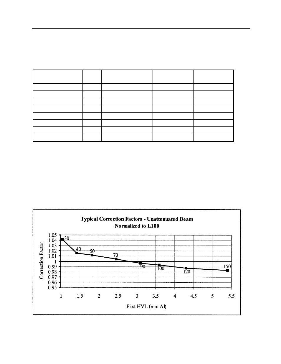
The typical correction factor curves for the unattenuated beam are shown below normalized to L100 in
Figure 5 and DV70 in Figure 6. All 96020C ion chambers must have an actual correction factor within ±
1.5% of the value shown in the curves at any point. Users receiving the standard calibration must request
a calibration factor at either L100 or DV70 to use the correction factors in these curves.
The numerical value shown beside each point is the kVp value of that point in the DV series of beam
qualities. Users making measurements in an unattenuated beam may use these values to easily obtain
the appropriate correction factor. For a more precise correction factor value, the user may calculate the
actual first HVL and locate the proper correction value on the curve.
Figure B-5.Energy Correction Factors for Model 96020C in Unattenuated Beam Normalized to L100