Flowserve CPXV fitted with WW User Manual
Page 23
CPXV - WW/CW USER INSTRUCTIONS ENGLISH 85392698 10-09
Page 23 of 36
flowserve.com
On product lubricated bearings it is recommended
that these are renewed at the diametrical clearance in
the as fitted condition stated in the following table:
Bearing bush material
Diametrical clearance in the
as fitted condition
All
0.5 mm (0.02 in.)
It is recommended to renew when wearing clearances
have doubled.
6.9 Disassembly
Refer to Safety section before dismantling the
pump.
For pumps with heating jackets, ensure that the
pump is cooled down correctly and sufficiently before
handling. After evacuating the tank and shutting off
the pump, the pumped liquid flows down through the
pump into the sump. After approximately 30 minutes
the heating steam line should be closed.
Before dismantling the pump for
overhaul, ensure genuine Flowserve replacement
parts are available.
Refer to sectional drawings for part numbers and
identification. See section 8, Parts lists and drawings.
6.9.1 Pump disassembly
a) Disconnect all auxiliary pipes and tubes where
applicable.
b) Disconnect all discharge and auxiliary pipework.
c) Remove coupling guard, disconnect coupling and
remove motor.
d) If oil lubricated unit, drain oil.
e) Remove nuts securing soleplate to foundations
and lift the complete unit clear.
f)
Record the gap between bearing carrier and
soleplate so that this setting can be used during
workshop assembly.
g) Remove suction pipe and/or strainer if fitted.
h) Remove all flushing lines as appropriate, casing
screws and discharge flange bolts.
i)
Remove pump casing.
j)
Remove pump casing and discharge flange
gaskets and discard. (A replacement gasket will
be required for assembly.)
k) Clean the gasket mating surfaces.
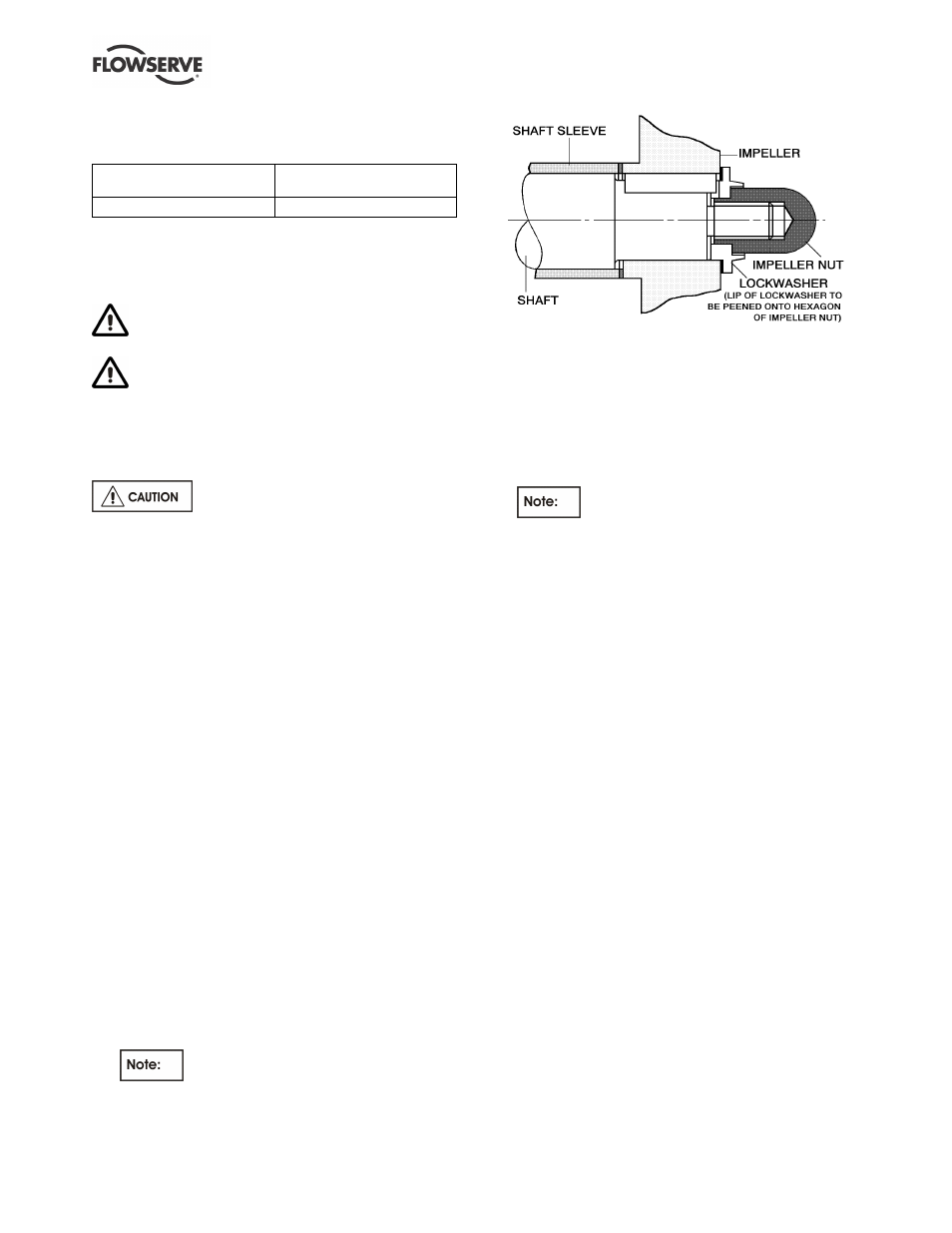
6.9.2 Impeller removal
a) Relieve impeller nut lockwasher from flat of impeller
nut. Remove impeller nut and lockwasher.
Where an inducer is fitted, this replaces
the impeller nut and lockwasher and is fitted with
Loctite 222.
b) Pull impeller off shaft.
c) Remove impeller key.
d) Remove impeller sealing gasket and discard. (A
new sealing gasket will be required for assembly.)
6.9.3 Support columns, shafts and bearings
a) Remove the two screws which fix the lower
bearing carrier to the lower support column.
b) Remove the lower bearing carrier.
If silicon carbide, carbon or high graphite
iron bearings are fitted extreme care should be taken
to avoid chipping or cracking these relatively brittle
components.
c) Unbolt and remove support column(s).
d) Unscrew the overhanging shaft section prior to
removing the next section of support column.
e) Any long length of shaft should be temporarily
supported to avoid bending or damage whilst
removing the muff coupling(s).
6.9.4 Bearings, seals and upper shaft
a) If a seal is fitted in the soleplate, determine its
type and remove the seal cover screws and any
accessible seal to shaft clamp screws as
appropriate.
b) Remove the bearing housing screws.
c) Drive out the labyrinth disk from the soleplate
(if fitted).
d) Pull the bearing housing and upper shaft assembly
out of the soleplate. Take care to support the long
shaft to avoid bending or damage to it and any
attached components.
e) Pull off the coupling and remove the coupling key.
f)
Unscrew the bearing outer nut (left hand thread).
g) Remove the drive side flinger and or labyrinth seal
(if fitted) from the shaft.
h) Slide the bearing carrier off of the bearing(s).
i)
Remove the bearing nut.
j)
Pull off the bearing(s).
k) Loosen any remaining seal to shaft clamp screws
and slide the seal(s) and seal covers off the shaft.
Any bearings or sleeves can then be pressed out/off
as required after first removing any retaining screws.