5 piping – Flowserve CPXV fitted with WW User Manual
Page 13
CPXV - WW/CW USER INSTRUCTIONS ENGLISH 85392698 10-09
Page 13 of 36
flowserve.com
4.5 Piping
Protective covers are fitted to the pipe
connections to prevent foreign bodies entering during
transportation and installation. Ensure that these
covers are removed from the pump before connecting
any pipes.
If sludge can build up in the sump it is
recommended to use a strainer with a maximum
opening size of 6 mm (0.24 in.) and a free surface
area greater than three times the pump suction area.
Maximum forces and moments allowed on the pump
flanges vary with the pump size and type. To minimize
these forces and moments that may, if excessive, cause
misalignment, hot bearings, worn couplings, vibration
and the possible failure of the pump casing, the
following points should be strictly followed:
•
Prevent excessive external pipe load
•
Never draw piping into place by applying force to
pump flange connections
•
Do not mount expansion joints so that their force,
due to internal pressure, acts on the pump flange
4.5.1 Suction and discharge pipework
In order to minimize friction losses and hydraulic
noise in the pipework it is good practice to choose
pipework that is one or two sizes larger than the
pump discharge. Typically main pipework velocities
should not exceed 3 m/s (9 ft/sec) on the discharge.
Never use the pump as a support for
piping.
Ensure piping and fittings are flushed
before use.
Ensure piping for hazardous liquids is arranged
to allow pump flushing before removal of the pump.
4.5.2 Discharge piping
A non-return valve should be located in the discharge
pipework to protect the pump from excessive back
pressure and hence reverse rotation when the unit is
stopped.
Fitting an isolation valve will allow easier maintenance.
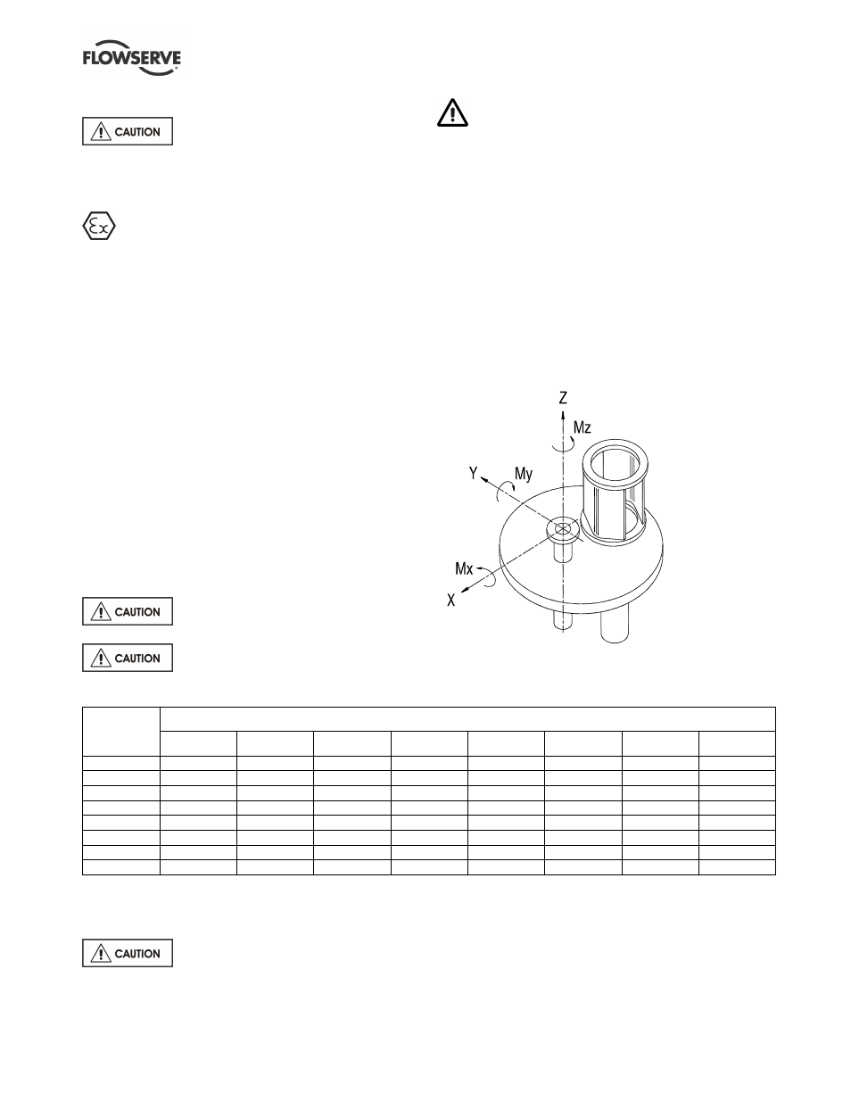
4.5.3 Maximum forces and moments allowed on
the main soleplate discharge flange
The table below uses the sign convention shown for the
pump soleplate discharge flange maximum forces and
moments. These are valid for a pump end up to 100 ºC
(212 ºF) and the soleplate on a rigid foundation.
Maximum forces (F) in kN (lbf) and moments (M) in kNm (lbf•ft)
Discharge
flange size
mm (in.)
Fx
Fy
Fz
Fr
Mx
My
Mz
Mr
40 (1.5)
0.71 (160)
0.58 (130)
0.89 (200)
1.28 (290)
0.46 (340)
0.23 (170)
0.35 (260)
0.62 (460)
50 (2.0)
0.71 (160)
0.58 (130)
0.89 (200)
1.28 (290)
0.46 (340)
0.23 (170)
0.35 (260)
0.62 (460)
80 (3.0)
1.07 (240)
0.89 (200)
1.33 (300)
1.93 (430)
0.95 (700)
0.47 (350)
0.72 (530)
1.28 (950)
100 (4.0)
1.42 (320)
1.16 (260)
1.78 (400)
2.56 (570)
1.33 (980)
0.68 (500)
1.00 (740)
1.80 (1 330)
125 (5.0)
1.95 (440)
1.58 (355)
2.45 (550)
3.50 (790)
1.93 (1 420)
0.98 (720)
1.36 (1 000)
2.56 (1 880)
150 (6.0)
2.49 (560)
2.05 (460)
3.11 (700)
4.48 (1010)
2.30 (1 700)
1.18 (870)
1.76 (1 300)
3.13 (2 310)
200 (8.0)
3.78 (850)
3.11 (700)
4.89 (1 100)
6.92 (1560)
3.53 (2 600)
1.76 (1 300)
2.58 (1 900)
4.71 (3 500)
250 (10.0)
5.34 (1 200)
4.45 (1 000)
6.67 (1 500)
9.63 (2 200)
5.02 (3 700)
2.44 (1 800)
3.80 (2 800)
6.75 (5 000)
4.5.4 Auxiliary piping
4.5.4.1 Pumps fitted with a soleplate packed gland
Ensure lubrication is supplied to the
gland packing.
4.5.4.2 Pumps fitted with mechanical seals
Seal housings/covers having an auxiliary quench
connection require connection to a suitable source of
liquid flow, low pressure steam or static pressure from
a header tank. Recommended pressure is 0.35 bar
(5 psi) or less.