6 casing, seal housing and fastener torques, 7 setting impeller clearance, 8 renewal clearances – Flowserve CPXV fitted with WW User Manual
Page 22
CPXV - WW/CW USER INSTRUCTIONS ENGLISH 85392698 10-09
Page 22 of 36
flowserve.com
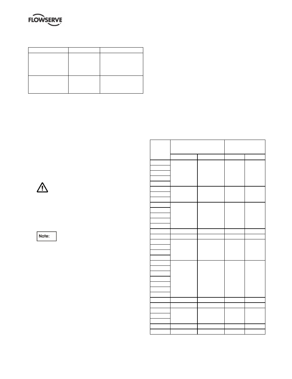
6.6 Casing, seal housing and fastener
torques
Fastener
Screw size
Torque Nm (lbf ft)
All except where
otherwise stated
M8
M10
M12
M16
M20
16 (12)
25 (18)
35 (26)
80 (59)
130 (96)
Impeller nut
M12
M16
M22
M24
16 (12)
41 (31)
106 (79)
135 (100)
6.7 Setting impeller clearance
The impeller is pre-set at the factory. This procedure
is required after the pump has been dismantled.
a) Before carrying out this procedure ensure that any
mechanical seal(s) fitted can tolerate a change in
their axial setting, otherwise it will be necessary to
dismantle the unit and reset the seal axial position
after adjusting the impeller clearance.
b) Disconnect the coupling if it has limited axial
flexibility.
c) Record the gap between the bearing carrier
[3240.1] and stool [3160] using feeler gauges.
d) Loosen the bearing carrier setscrews [6570.3] and
back off the bearing carrier adjusting screws
[6570.4] by 2 mm (0.08 in.).
Some mechanical seal types may be
impaired if moved more than 0.5 mm (0.02 in.)
from their nominal setting.
e) Tighten the bearing carrier screws evenly, drawing
the bearing carrier towards the soleplate, until the
impeller contacts the pump casing. Turn the shaft,
during this procedure, until a detectable rub is
obtained. This is the zero clearance position.
The shaft must be turned in the direction
indicated on the casing and soleplate.
f)
Set a dial indicator to zero on the shaft end or
measure the bearing carrier [3240.1] to stool
[3160] gap and record the measurement.
g) Slacken the bearing carrier setscrews [6570.3].
h) Tighten adjusting screws [6570.4] evenly (about
one flat at a time) drawing the bearing carrier away
from the soleplate until the impeller contacts the
impeller rear cover. Turn the shaft during this
procedure until a detectable rub is obtained. The
dial indicator or feeler gauge shows the
maximum float position from the zero clearance
position.
i)
Evenly tighten the bearing carrier setscrews [6570.3]
keeping the dial indicator or feeler gauges reading
the correct setting. Then tighten the hexagon nuts
[6580.1] to lock the jacking screws in position.
j)
Compare the nominal and final gaps between the
bearing carrier and soleplate to check if the
movement of the shaft permits sufficient clearance
in the axial direction. The impeller design
clearance is midway. Re-position the seal to
correct this.
k) Check that the shaft can turn freely without binding.
l)
If a cartridge seal is fitted, reset it at this point.
m) Ensure the coupling distance between shaft ends
(DBSE) is correct. Reset/re-align if necessary.
6.8 Renewal clearances
As wear takes place between the impeller and casing
ring the overall efficiency of the pump set will
decrease. To maintain optimum efficiency it is
recommended that the wearing clearances tabulated
below are maintained.
Wearing clearances
Impeller hub diameter
(mm)
Diametral ring or
casing clearance
mm)
Pump
size
Front
Back
Front
Back
65-100
50-125
50-160
40-200
40-250
82.54/82.45
82.54/82.45
0.64/0.46
0.64/0.46
32-125
32-160
32-200
70.54/70.47
70.54/70.47
0.60/0.46
0.60/0.46
65-125
65-160
50-200
50-250
50-315
93.54/93.45
93.54/93.45
0.64/0.46
0.64/0.46
80-125
111.47/111.38
93.54/93.45
0.71/0.53
0.64/0.46
25-161
55.54/55.47
55.54/55.47
0.60/0.46
0.60/0.46
80-160
65-200
65-250
65-315
111.47/111.38 111.47/111.38
0.71/0.53
0.71/0.53
100-160
100-200
100-250
125-250
100-315
125-315
100-400
152.47/152.37 152.47/152.37 0.67/0.53
0.67/0.53
125-225
168.10/168.00 168.10/168.00 0.80/0.60
0.80/0.63
125-400
184.00/183.90 184.00/183.90 0.71/0.53
0.71/0.53
150-250
150-315
150-400
209.40/209.30 209.40/209.30 0.80/0.60
0.80/0.63
200-401
269.24/269.14 269.24/269.14 0.85/0.65
0.85/0.65
150-500
219.47/219.37 219.47/219.37 0.73/0.53
0.73/0.53