Flowserve S-series PolyChem User Manual
Page 44
USER INSTRUCTIONS POLYCHEM S-SERIES ENGLISH 71569207 11-08
Page 44 of 52
flowserve.com
6.10.2.1 Cartridge mechanical seals
Sleeve design 1 and 2
Review the seal assembly instructions and drawings
provided by the seal manufacturer.
a) If the pump is equipped with a sleeve [2400], slip it
into place over the impeller end of the shaft [2100].
b) Install a nose cone on the end of the shaft and
then slide the cartridge seal [4200] onto the shaft
until it lightly touches the bearing housing [3200]
or adapter [1340].
c) Install the rear cover plate [1220] to the bearing
housing (Group A and 1) or the bearing housing
adapter (Group B, C and 2) by using the cap
screws [6570.2].
d) Install the cartridge seal gland to the rear cover
plate [1220] using studs [6572.2] and nuts [6580.2].
e) Install the impeller [2200] as instructed in section 6.7.
f) Tighten set screws on the seal to lock the rotating
unit to the shaft. Finally, remove centering clips
from the seal.
Sleeve design 3
Review the seal assembly instructions and drawings
provided by the seal manufacturer.
a) Loosely attach the cartridge seal gland to the rear
cover plate [1220] using studs [6572.2] and nuts
[6580.2].
b) Install the rear cover plate [1220] to the bearing
housing (Group 1) or the bearing housing adapter
(Group 2) by using the cap screws [6570.2].
c) Install new tolerance rings into each end of the
sleeve [2400]. (See Figure 6-22.)
Figure 6-22
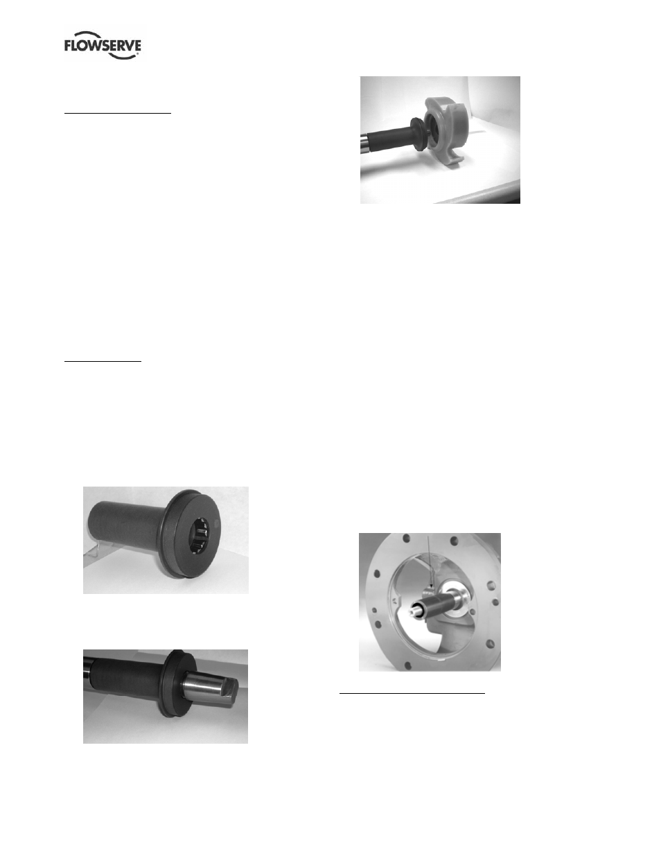
d) Install sleeve assembly onto shaft [2100] utilizing
the nose cone to ensure the end of the sleeve
remains flush with the end of the shaft. (See
Figure 23.)
Figure 6-23
e) Install O-ring onto flange portion of the sleeve.
(See Figure 6-24.)
Figure 6-24
f)
Install the impeller [2200] as instructed in section 6.7.
g) Tighten the nuts [6580.2] used to attach the
gland to the cover plate [1220].
h) Tighten set screws on the seal to lock the rotating
unit to the shaft. Finally, remove centering clips
from the seal.
6.10.2.2 Component type mechanical seal -
sleeve design 1 and 2
Review the seal assembly instructions and drawings
(seal set dimension) provided by the seal manufacturer.
In order to properly set a component seal it is necessary
to first locate the shaft in its final axial position. This is
accomplished in the following manner:
a) Install the rear cover plate [1220] to the bearing
housing (Group A and 1) or the bearing housing
adapter (Group B, C and 2) by using the cap
screws [6570.2].
b) Install and set the impeller [2200] clearance as
outlined in section 6.6. Put bluing on the shaft/
sleeve in the area near the face of the seal
chamber [rear cover 1220]. Scribe a mark on the
shaft at the face of the seal chamber. (Figure 6-25.)
c) Remove the impeller and seal chamber (rear cover)
following the instructions given in section 6.8 and
install a nose cone onto the end of the shaft.
Figure 6-25
Single internal seal installation
d) Place the gland [4120], gland gasket [4590.3],
stationary seat and a second gland gasket
[4590.3] onto the shaft until it lightly touches the
bearing housing (Group A and 1) or adapter
(Group B, C and 2).