Flowserve S-series PolyChem User Manual
Page 19
USER INSTRUCTIONS POLYCHEM S-SERIES ENGLISH 71569207 11-08
Page 19 of 52
flowserve.com
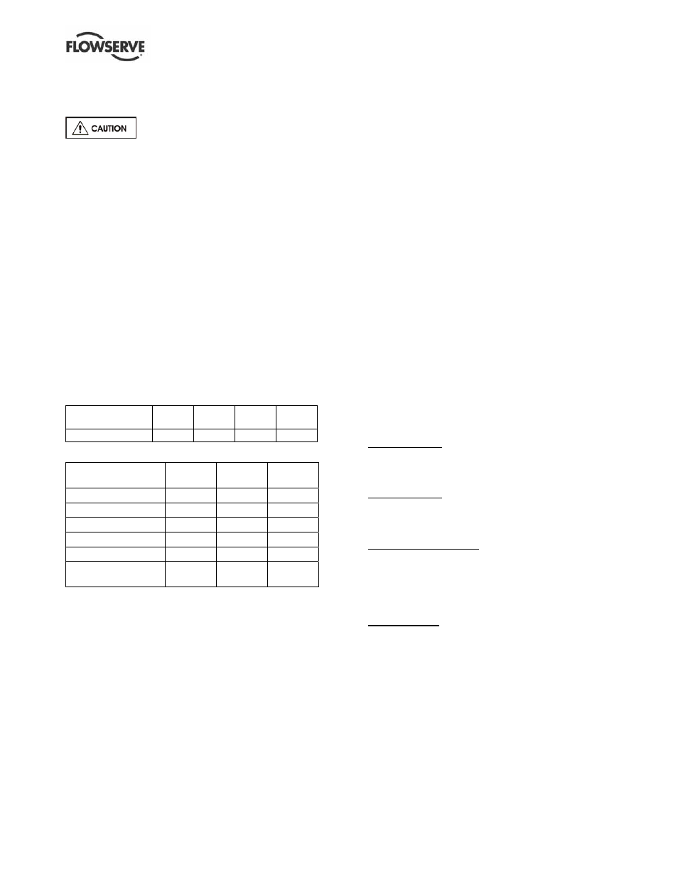
4.6.4 Allowable nozzle loads
4.6.4.1 Introduction
Never use the pump as a support for
piping.
Maximum forces and moments allowed on pump flanges
vary based on the pump size. When these forces and
moments are minimized, there is a corresponding
reduction in misalignment, hot bearings, worn couplings,
vibration and possible failure of the pump casing. The
following points should be strictly followed:
• Prevent excessive external pipe load
• Never draw piping into place by applying force to
pump flange connections
• Do not mount expansion joints so that their force,
due to internal pressure, acts on the pipe flange
The PolyChem product line is designed to meet the
requirements of ANSI/HI 9.6.2. Allowable nozzle
loads for ISO pumps may be calculated using
ANSI/HI 9.6.2 by selecting a comparable pump size.
Figure 4-9: Casing material correction factors –
Material Group No. 1.0
Temperature ˚C
( ˚F)
-29
(-20)
38
(100)
93
(200)
150
(300)
Correction
factors 0.89 0.89 0.83 0.78
Figure 4-10: Baseplate correction factors
Base type
Grouted
Bolted
Stilt
mounted
Type A
1.0
0.7
0.65
Type B - Polybase
1.0
n/a
0.95
Type C
n/a
1.0
1.0
Type D
1.0
0.8
0.75
Type E - PIP
1.0
0.95
n/a
Polyshield -
baseplate/foundation
1.0 n/a n/a
4.6.4.2 PolyChem S-series pumps
The following steps are based upon ANSI/HI 9.6.2.
All information necessary to complete the evaluation
is given below. For complete details please review
the standard.
a) PolyChem S-series pumps are only manufactured
from Ductile Iron. For reference the “Material
Group No.” for this material is 1.0.
b) Find the “Casing Material Correction Factor” in
Figure 4-9 based upon the operating temperature.
Interpolation may be used to determine the
correction factor for a specific temperature.
c) Find the “Baseplate Correction Factor” in Figure
4-10. The correction factor depends upon how the
baseplate is to be installed.
d) Locate the pump model being evaluated in Figure
4-14 and multiply each load rating by the casing
correction factor. Record the adjusted Figure 4-14
loads.
e) Locate the pump model being evaluated in
Figures 4-15 and 4-16 and multiply each load
rating by the baseplate correction factor. Record
the adjusted Figure 4-15 and 4-16 loads.
f) Compare the adjusted Figure 4-14 values (step
D) to the values shown in Figure 4-13. The lower
of these two values should be used as the
adjusted Figure 4-13 values. (The HI standard
also asks that Figure 4-13 loads be reduced if
Figure 4-15 or 4-16 values are lower. Flowserve
does not follow this step.)
g) Calculate the applied loads at the casing flanges
according to the coordinate system found in
Figure 4-11. The 12 forces and moments
possible are Fxs, Fys, Fzs, Mxs, Mys, Mzs, Fxd,
Fyd, Fzd, Mxd, Myd and Mzd. For example, Fxd
designates force in the “x” direction on the
discharge flange. Mys designates the moment
about the “y”-axis on the suction flange.
h) Figure 4-12 gives the acceptance criteria
equations. For long coupled pumps, equation
sets 1 through 5 must be satisfied. For C-Face
pumps (Ultralign), only equation sets 1 and 2
must be satisfied.
i)
Equation set 1. Each applied load is divided by
the corresponding adjusted Figure 4-13 value.
The absolute value of each ratio must be less
than or equal to one.
j)
Equation set 2. The summation of the absolute
values of each ratio must be less than or equal to
two. The ratios are the applied load divided by
the adjusted Figure 4-14 values.
k) Equation sets 3 and 4. These equations are
checking for coupling misalignment due to nozzle
loading in each axis. Each applied load is
divided by the corresponding adjusted load from
Figure 4-15 and 4-16. The result of each
equation must be between one and negative one.
l)
Equation set 5. This equation calculates the total
shaft movement from the results of equations 3 and
4. The result must be less than or equal to one.