8 pump removal and disassembly – Flowserve S-series PolyChem User Manual
Page 35
USER INSTRUCTIONS POLYCHEM S-SERIES ENGLISH 71569207 11-08
Page 35 of 52
flowserve.com
The above technique is only applicable if all
of the original pump components are reinstalled. If
the casing, cover, impeller or shaft is replaced this
method must not be used.
6.8 Pump removal and disassembly
6.8.1 Pump removal
a) Before performing any maintenance, disconnect the
driver from its power supply and lock it off line.
Lock out power to driver to prevent
personal injury.
b) Close the discharge and suction valves, and
drain all liquid from the pump.
c) Close all valves on auxiliary equipment and
piping, then disconnect all auxiliary piping.
d) Decontaminate the pump as necessary.
If Flowserve PolyChem S-series
pumps contain dangerous chemicals it is
important to follow plant safety guidelines to
avoid personal injury or death.
e) Remove the coupling guard. (See section 5.5.)
f) Remove the spacer from the coupling.
g) Remove casing fasteners [6580.1].
h) Remove the fasteners holding the bearing
housing foot to the baseplate.
i)
Move the power end, rear cover, and seal chamber
assembly away from the casing.
The power end and rear cover
assembly is heavy. It is important to follow plant
safety guidelines when lifting it.
j)
Transport the assembly to the maintenance shop.
6.8.2 Pump disassembly
a) Remove coupling hub from the pump shaft [2100].
Do not apply heat to the impeller.
This could damage the liner plus if liquid is
entrapped in the hub, an explosion could occur.
b) Using the shaft key [6700], mount the impeller
wrench from the Flowserve impeller tool kit (Figure
6-1) to the end of the shaft. With the wrench handle
pointing to the left when viewed from the impeller
end, grasp the impeller [2200] firmly with both
hands (wear heavy gloves). By turning the impeller
in the clockwise direction move the wrench handle
to the 11 o’clock position and then spin the impeller
quickly in a counter-clockwise direction so that the
wrench makes a sudden impact with a hard surface
on the bench. After several sharp raps, the impeller
should be free. Unscrew the impeller and remove
from the shaft. Discard the impeller O-ring [4610.8].
c) If a cartridge type mechanical seal [4200] is used,
the spacing clips or tabs should be installed prior
to loosening the set screws which attaches the
seal to the shaft or removing it from the cover.
This will ensure that the proper seal compression
is maintained.
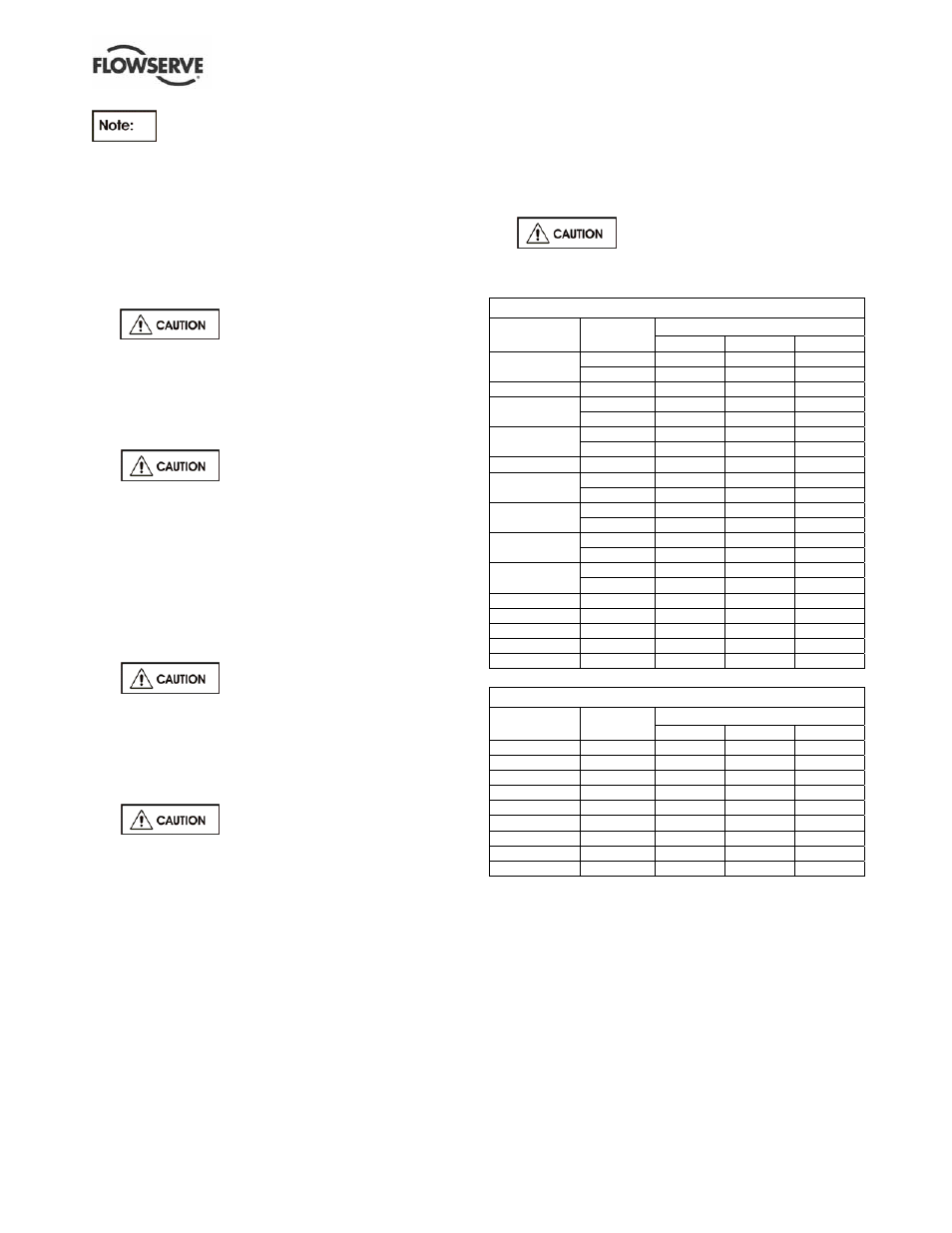
Three sleeve designs are utilized
on the PolyChem S-series pump. The style of
sleeve depends on the pump model/impeller.
ANSI
Sleeve design
Pump Impeller
1 2 3
Closed X
1.5X1-6
Open X X
1.5X1-8 Closed X
Closed X
3X1.5-6
Open X X
Closed X
3X2-6
Open X X
2X1-10 Closed
X
Closed
X
3X2-10
Open X X
Closed X
3X2-10HD
Open X X
Closed X
4X3-10
Open X X
Closed X
4X3-10HD
Open
X X
3X2-13 Open
X
3X2-13HD Open
X
4X3-13 Open
X
4X3-13HD Open
X
6X4-13HD Open
X
ISO
Sleeve design
Pump Impeller
1 2 3
PS32-160 Closed
X
PS65-160 Closed
X
PS40-200 Closed
X
PS32-250 Closed
X
PS50-250 Closed
X
PS65-250 Closed
X
PS50-315 Open
X
PS65-315 Open
X
PS100-315 Open
X
Design 1 standard is silicon carbide although metallic
versions of the sleeve are available. Depending on
the seal design, if set screws are utilized to attach the
rotary unit and they fall onto the sleeve you must
replace the standard sleeve (silicon carbide) with a
metal sleeve or convert to a solid shaft.
Design 2 standard is a metallic hook sleeve.