Flowserve S-series PolyChem User Manual
Page 33
USER INSTRUCTIONS POLYCHEM S-SERIES ENGLISH 71569207 11-08
Page 33 of 52
flowserve.com
Tighten the impeller with the impeller wrench from the
Flowserve impeller tool kit. To do this, grasp the
impeller in both hands and, with the impeller wrench
handle to the left (viewed from the impeller end of the
shaft - Figure 6-4) spin the impeller forcefully in a
clockwise direction to impact the impeller wrench
handle on the work surface to the right. (Figure 6-5.)
Do not attempt to tighten the impeller
on the shaft by hitting the impeller with a hammer or
any other object or by inserting a pry bar between the
impeller vanes. Serious damage to the impeller may
result from such actions.
Figure 6-4
Figure 6-5
The preferred impeller setting location is midway
between the casing and the rear cover. This is
accomplished by loosening the set screws [6570.3] and
rotating the bearing carrier [3240]. Turn the bearing
carrier counter-clockwise until the impeller comes into
light rubbing contact with the rear cover. Rotating the
shaft at the same time will accurately determine this
zero setting. Using a felt tip pen place a reference mark
on both the bearing housing and the carrier.
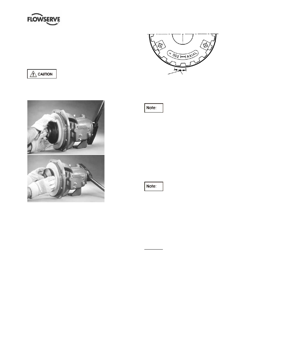
Now, rotate the bearing carrier clockwise while counting
the number of indicator patterns (Figure 6-6) until you
come into light rubbing contact with the casing. As
before, rotating the shaft will help in establishing when
contact is made. Rotating the bearing carrier the width
of one of the indicator patterns cast into the bearing
carrier moves the impeller axially 0.1 mm (0.004 in.).
Generally speaking the total axially clearance will be
approximately 5.0 mm (0.20 in.). Once you know the
total axial clearance, that number should be split in
half and then divided by 0.10 mm (0.004 in.) to
determine the number of indicator patterns that the
bearing carrier should be rotated.
Figure 6-6
Rotate the bearing carrier counter-clockwise the
required amount to get the desired clearance.
Lastly, uniformly tighten the set screws
[6570.3] in incremental steps up to the final torque
value to lock the bearing carrier in place.
An alternate approach for setting the impeller is to set
it off the rear cover. Turn the bearing carrier counter-
clockwise until the impeller comes into light rubbing
contact with the rear cover. Rotating the shaft at the
same time will accurately determine this zero setting.
Using a felt tip pen place a reference mark on both
the bearing housing and the carrier. The desired
clearance setting is 2.5 mm (0.10 in.). Rotate the
bearing carrier clockwise 25 indicator patterns to get
the desired clearance.
Lastly, uniformly tighten the set screws
[6570.3] in incremental steps up to the final torque
value to lock the bearing carrier in place.
Tightening the set screws [6570.3] will cause the
impeller to move 0.05 mm (0.002 in.) closer to the rear
cover because of the internal looseness in the bearing
carrier threads. This change is considered insignificant
to the impeller clearance setting and need not be
accounted for when setting a closed vane impeller.
Example. The impeller of a pump has been replaced
and as a result the impeller setting must be reset. Since
the preferred approach is to locate the impeller midway
between the casing and the cover the first step is to
determine the amount of axial clearance that is
available. Turn the bearing carrier counter-clockwise
until the impeller comes into light rubbing contact with
the rear cover. Flowserve suggests that a felt tip pen be
used to mark an initial reference point on the bearing
housing and the bearing carrier. Rotate the bearing
carrier clockwise until the impeller comes into light
contact with the casing keeping track of the number of
indicator patterns moved, which in this example is 46.
This number of indicator patterns corresponds to a total
axial clearance of 4.6 mm (0.18 in.).
Indicator
pattern
Rotation equivalent
to 0.1 mm (0.004 in.)
axial movement