5 tools required, 6 fastener torques – Flowserve S-series PolyChem User Manual
Page 32
USER INSTRUCTIONS POLYCHEM S-SERIES ENGLISH 71569207 11-08
Page 32 of 52
flowserve.com
6.5 Tools required
A typical range of tools that will be required to
maintain these pumps is listed below.
Standard hand tools
• Hand
wrenches
(Metric and SAE)
• Socket
wrenches (Metric and SAE)
• Allen
wrenches
(Metric and SAE)
• Soft
mallet
• Screwdrivers
Specialized equipment
• Bearing
pullers
• Bearing induction heaters
• Dial
indicators
• Spanner
wrench
• Flowserve impeller tool kit (ISO and ANSI)
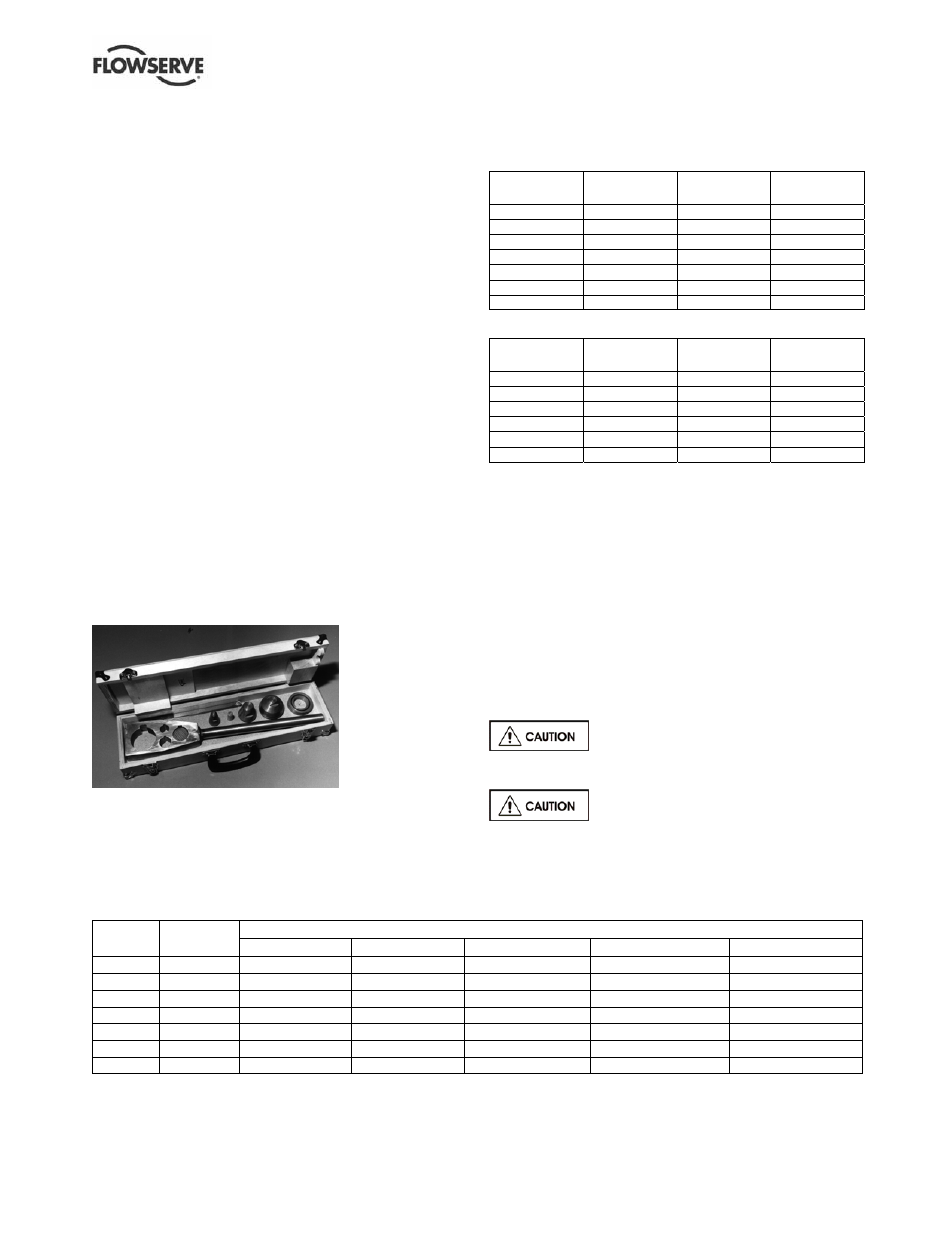
To simplify maintenance, it is recommended that the
Flowserve impeller tool kit (shown in Figure 6-1) is used.
This tool kit includes an impeller wrench, which
simplifies installation and removal of the impeller. It also
contains “nose cones” which protect shaft threads and
mechanical seal O-rings during maintenance.
This tool kit can be ordered from your local Flowserve
sales engineer or from a Flowserve distributor or
representative.
Figure 6-1
6.6 Fastener torques
Non-metallic gaskets incur creep relaxation – before
commissioning the pump, check and retighten
fasteners to tightening torques stated.
Figure 6-3: Recommended flange fastener
torques - SI (US)
ISO pump with PN16 flanges
Flange size
mm (in.)
Number
of bolts
Bolt diam.
mm (in.)
Bolt torque
Nm (lbf•ft)
32 (1.3)
4
16 (0.63)
91 (67)
40 (1.6)
4
16 (0.63)
99 (73)
50 (2.0)
4
16 (0.63)
124 (91)
65 (2.6)
4
16 (0.63)
153 (112)
80 (3.1)
8
16 (0.63)
110 (81)
100 (3.9)
8
16 (0.63)
135 (99)
125 (4.9)
8
16 (0.63)
185 (137)
ANSI pump with Class 150 flanges
Flange size
in. (mm)
Number
of bolts
Bolt diam.
in. (mm)
Bolt torque
Nm (lbf•ft)
1 (25.4)
4
0.50 (12)
34 (25)
1 ½ (38.1)
4
0.50 (12)
75 (55)
2 (50.8)
4
0.63 (16)
102 (75)
3 (76.2)
4
0.63 (16)
149 (110)
4 (101.6)
8
0.63 (16)
129 (95)
6 (152.4)
8
0.75 (19)
169 (125)
6.7 Setting impeller clearance and
impeller replacement
A new impeller O-ring [4610.8] must be installed
whenever the impeller has been removed from the
shaft. Impeller clearance settings for open style
impellers may be found in section 5.3. Impeller
balancing instructions may be found in section 6.8.
6.7.1 Installation and clearance setting for closed
vane impellers
Install the impeller [2200] by screwing it onto the shaft
(use heavy gloves) until it firmly seats against the
shaft/sleeve face.
The impeller could have sharp edges,
which could cause an injury. It is very important to
wear heavy gloves.
Do not adjust the impeller clearance
with the seal set. Doing so may result in seal leakage
and/or damage.
Figure 6-2: Recommended pump fastener torques - SI (US)
Size – Lubricated torque Nm (lbf•ft)
Item Comment
Group 1
Group A
Group 2
Group B
Group C
6570.2
3/8 in. - 27 (20)
10 mm - 27 (20)
3/8 in. - 27 (20)
10 mm - 27 (20)
10 mm - 27 (20)
6570.3
3/8 in. - 16 (12)
3/8 in. - 16 (12)
1/2 in. - 41 (30)
12 mm - 41 (30)
12 mm - 41 (30)
6570.4
1/2 in. - 54 (40)
12 mm - 54 (40)
3/4 in. - 217 (160)
16 mm - 108 (80)
16 mm - 108 (80)
6570.5
N/A
N/A
1/2 in. - 54 (40)
12 mm - 54 (40)
12 mm - 54 (40)
6570.12
#10 - 5 (4)
#10 - 5 (4)
#10 - 5 (4)
N/A
N/A
6580.1
1/2 in. - 34 (25)
12 mm - 34 (25)
5/8 in. - 61 (45)
16 mm - 61 (45)
16 mm - 61 (45)
6580.2
3/8 in. - 14 (10)
10 mm - 14 (10)
1/2 in. - 34 (25)
12 mm - 34 (25)
12 mm - 34 (25)
Note: for non-lubricated threads, increase the value by 25 %.