Enclosure requirements – Fire Magic Aurora Built-In Combo Grill A830i User Manual
Page 12
12
FOR YOUR SAFETY, you must provide the openings listed
below for drainage, replacement air, and cross-ventilation
of any storage area exposed to possible leakage from gas
connections, the unit, or propane cylinders.
One side of the enclosure can be left completely open to the
outside, OR 4 ventilation openings must be created:
NATURAL GAS INSTALLS
Two of the openings are to be at the top level (approx. 4"
below the countertop) and on opposite walls of the enclosure.
2 more openings must be at the fl oor level (no more than
5" above the fl oor) and on opposite sides of the enclosure.
Each opening must have a minimum of 10 sq. in. of free
area. To achieve the proper ventilation, you may drill a series
of holes, omit the grout from masonry joints, or replace a
brick with a hardware cloth screen. If the fl oor in the cabinet
is raised and the space beneath the cabinet is open to the
outside, the lower ventilation openings may be in the fl oor.
Reference Fig. 12-1.
PROPANE GAS INSTALLS
(HOUSEHOLD & CYLINDER)
Two of the openings are to be at the cylinder valve level
(approx. 16" above the fl oor) and on opposite walls of the
enclosure. 2 more openings must be at the fl oor level (no
more than 5" above the fl oor) and on opposite sides of the
enclosure. Each opening must have a minimum of 10 sq.
in. of free area. To achieve the proper ventilation, you may
drill a series of holes, omit the grout from masonry joints, or
replace a brick with a hardware cloth screen. If the fl oor in
the cabinet is raised and the space beneath the cabinet is
open to the outside, the lower ventilation openings may be
in the fl oor. Reference Fig. 12-1.
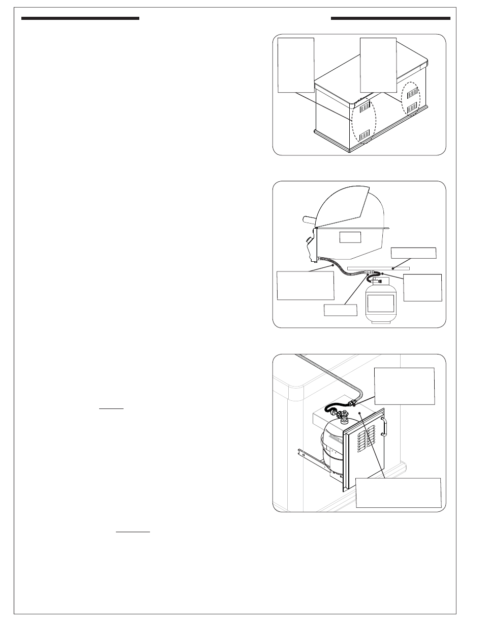
WHEN A PROPANE CYLINDER IS USED
When a propane cylinder is installed inside of the enclosure,
the guidelines below MUST be followed. FAILURE TO DO SO
MAY CAUSE DAMAGE TO YOUR UNIT AND/OR PERSONAL
INJURY. Reference Fig. 12-2 for an example.
• The propane cylinder (and any door/tray it is located
in) MUST be located on the gas grill side of the unit
(right side). DO NOT locate the propane cylinder on the
charcoal side of the unit.
• Only a C.S.A. listed stainless steel connector can be
connected to the grill.
• The regulator/hose assembly coming from the propane
cylinder can only be connected to the above mentioned
grill fl ex connector. DO NOT connect the regulator/
hose assembly directly to the grill. An adapter will
be required.
• A heatshield must be installed to protect the regulator/
hose assembly and propane cylinder valve.
• RHP offers a propane cylinder door with tank tray to
meet the cylinder install requirements. See Fig. 12-3.
Fig. 12-2 Propane cylinder orientation
Fig. 12-1 Ventilation detail
Nat. gas
installs
(repeat for
opposite
side)
Fig. 12-3 Optional RHP door w/ tank tray
Adapter
L.P. gas
installs
(repeat for
opposite
side)
Grill
C.S.A. listed
stainless steel
fl ex connector
Heatshield
Regulator/
hose
assembly
L.P.
cylinder
Cylinder & regulator/
hose assembly
protected by heatshield
Equipped with
adapter for hose
assembly and
fl ex connector
ENCLOSURE REQUIREMENTS
REV 0 - 1412031335
L-C2-452