Recommended accessories, Calibration, Limited warranty – Fieldpiece SMAN320 - 3-Port Digital Manifold User Manual
Page 2: Obtaining service, Refrigerants, Using different refrigerants, Firmware updates, Easy view micron gauge model svg3, Pipe clamp thermocouple model atc1, Temperature
11
16
12
17
13
18
14
19
15
20
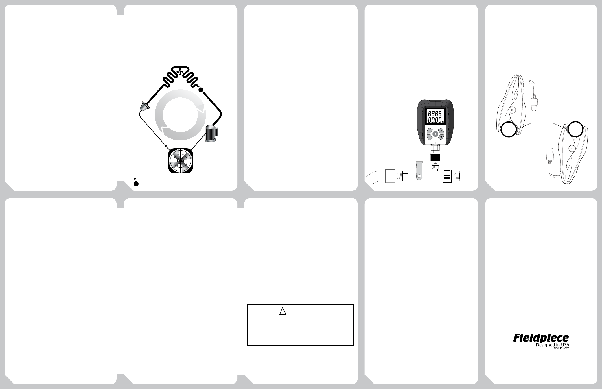
What is Superheat and Subcooling?
Why Do I Need to Measure It?
Superheat is the difference between the
actual temperature of the refrigerant (gas) as
it leaves the evaporator and the boiling point
of the refrigerant. After boiling, the refrigerant
continues to heat up. The number of degrees it
“heats up” after boiling is called the superheat.
Under worst case conditions (low load for fixed
orifice systems), the refrigerant in the evaporator
boils off near the end of the evaporator coil. To
make sure liquid doesn’t enter the compressor
under the worst case condition (low load),
the refrigerator or A/C manufacturers publish
charts indicating what the superheat should be
at a given indoor wet bulb measurement and
outdoor air temperature.
Measuring superheat is your best indication
on a fixed orifice system of the proper
refrigerant charge and operating conditions.
If everything else is working properly and the
actual superheat is too high, add refrigerant. If
it’s too low, evacuate refrigerant.
Subcooling is the difference between the
boiling point of the refrigerant in the condenser
and the actual temperature of the refrigerant
as it leaves the condenser. The degrees that the
refrigerant “cools down” below the boiling point
is the subcooling. Under worst case scenario
(low load for TXV) the subcooling will continue
to rise. If the subcooling rises too high, liquid
may be backed into the compressor causing
damage and catastrophic failure. See www.
fieldpiece.com for more technical articles.
Location of Subcooling Test
Location of Superheat Test
Refrigerants
The P-T charts of the following 45 refrigerants come pre-
programmed into your SMAN. In your SMAN the refrigerants are listed
in order of most commonly used. Here, they are listed in numerical
order for easy reference.
R11, R113, R114, R12, R123, R1234YF, R124, R125, R13, R134A, R22,
R23, R32, R401A(MP39), R401B, R402A, R402B, R404A, R406A, R407A,
R407C, R407F, R408A, R409A, R410A, R414B (Hotshot), R416A, R417A,
R417C (HOT SHOT 2), R420A, R421A, R421B, R422A, R422B(NU22B),
R422C(Oneshot), R422D, R424A, R427A, R434A(RS-45), R438A(MO99),
R500, R502, R503, R507A, R508B (Suva95)
Using Different Refrigerants
You can use your manifold with different refrigerants. Be sure to
purge your manifold and hoses before connecting to a system with a
different refrigerant.
Firmware Updates
Your SMAN320 firmware can be updated in the field to ensure you
always have the most up-to-date features for your manifold. Just go
to www.fieldpiece.com to periodically check for the latest firmware
version. If a newer version is available, follow the download link and
installation instructions on the website. Connect your SMAN320 to the
PC via a mini-USB to USB cable (not included) to install the update on
your SMAN.
To check your current firmware version, power off your SMAN320.
Press and hold the blue power button for about 6 seconds. The SMAN320
firmware version will show in the top right corner of the display (X.XX).
Recommended
Accessories
Easy View Micron Gauge
Model SVG3
Measure the depth of the vacuum in microns
of mercury to verify all moisture and non-
condensibles have been removed from the
system. For the most accurate reading, connect
directly to a service port on the system or to a
Schrader core removal tool (illustrated below).
Pipe Clamp Thermocouple
Model ATC1
Measure suction line and liquid line pipe
temperatures quickly and easily. Using a pipe
clamp thermocouple makes it easy to check the
superheat and/or subcooling of the system to
verify proper charge.
Calibration
Temperature
To calibrate your SMAN temperature
thermocouples, adjust the pot on the front
of the meter labeled SLT Cal or LLT Cal. The
best way to calibrate is to match to a known
temperature. Ice water is very close to 32°F and
is readily available. Accuracies of one degree or
better are easily obtained.
1 Stabilize a large cup of ice water by stirring. Pure, distilled water
will be the most accurate.
2 Immerse the temp probe in ice water from SLT and adjust the
SLT Cal pot with a flathead screwdriver and let it stabilize, keep
stirring.
3 Repeat Step 3 for temp probe in LLT.
Pressure Zeroing
To calibrate your SMAN320 pressure sensors
to atmospheric pressure, ensure that your
SMAN320 is disconnected from any pressure
source and at equilibrium with the ambient
pressure.
1 Press the CAL Atmospheric Pressure button and your SMAN320
will set the zero point of pressure to the ambient pressure.
Advanced Pressure Calibration
Your SMAN320 has the ability to perform a
linear adjustment of the pressure sensors based
on refrigerant type, temperature, and pressure.
Calibration setup: For best results, first perform both the
Temperature and Pressure Zeroing procedures. See Calibration
section for details. This will ensure pressure readings are zeroed
and thermocouple is properly calibrated to the SLT port of the
SMAN. Calibration to LLT port is not necessary for this calibration.
The refrigerant cylinder should be stored in a stable ambient
environment for at least 24 hours before calibration.
1 Plug in a Type K thermocouple into SLT. (A bead type
thermocouple, like the ATB1, is recommended.)
2 Connect the SMAN320 to a refrigerant cylinder of a known,
single refrigerant using an EPA approved service hose. Be sure
to open both HIGH and LOW side valves on your manifold and
cap the unused ports. (If caps are not available you can connect
both ends of a refrigerant hose to the two unused caps. Note:
Some refrigerant will remain in the hoses which will need to be
recovered.)
3 Press the REFRIGERANT button to match the refrigerant of the
cylinder you are using.
4 Attach bead-type thermocouple to the side of the cylinder using
tape. It is recommended to attach in the middle of the cylinder.
Important: Let the temperature of the thermocouple stabilize to
the refrigerant temperature for 1 to 2 minutes or until stable.
5 Open the refrigerant cylinder. The pressure inside cylinder should
now be displayed on both HIGH and LOW side pressure sensors.
6 Press the CAL Test Pressure button. If successful, "Good" will
display for 3 seconds. If failed, "Err" will display for same time.
Your SMAN checks with its built-in P-T charts to compare the
temperature of the refrigerant in the tank to the vapor saturation
temperature based on the refrigerant you selected. If the measured
pressures on your SMAN are within ±3psi of the P-T chart pressure
corresponding to the vapor saturation temperature, the SMAN will
adjust the pressure sensor linearity to match the P-T chart.
Possible causes of failed "Err" pressure calibration:
1. Refrigerant tank was not stored in stable ambient conditions for at
least 24 hours.
2. Thermocouple attached to refrigerant tank was not properly
calibrated to SLT port of SMAN.
3. Thermocouple was plugged into wrong port LLT instead of SLT.
4. Incorrect refrigerant was selected on the SMAN.
Limited Warranty
This meter is warranted against defects
in material or workmanship for one year
from date of purchase from an authorized
Fieldpiece dealer. Fieldpiece will replace or
repair the defective unit, at its option, subject
to verification of the defect.
This warranty does not apply to defects
resulting from abuse, neglect, accident,
unauthorized repair, alteration, or unreasonable
use of the instrument.
Any implied warranties arising from the sale of
a Fieldpiece product, including but not limited
to implied warranties of merchantability and
fitness for a particular purpose, are limited to
the above. Fieldpiece shall not be liable for loss
of use of the instrument or other incidental or
consequential damages, expenses, or economic
loss, or for any claim of such damage, expenses,
or economic loss.
State laws vary. The above limitations or
exclusions may not apply to you.
Obtaining Service
Email Fieldpiece warranty department at
[email protected] for current fixed
price repair service. Send check or money
order made out to Fieldpiece Instruments for
the amount quoted. If your meter is under
warranty there will be no cost for the repair/
replacement. Send your meter, freight prepaid,
to Fieldpiece Instruments. Send proof of date
and location of purchase for in-warranty service.
The meter will be repaired or replaced, at the
option of Fieldpiece, and returned via least cost
transportation.
For international customers, warranty for
products purchased outside of the U.S. should
be handled through local distributors. Visit our
website to find your local distributor.
www.fieldpiece.com
© Fieldpiece Instruments, Inc 2014; v05
High Side
Low Side
TXV
Compressor
Direction of
Refrigerant
Flow
Condenser
Evaporator
!
WARNINGS
DO NOT APPLY MORE THAN 800 PSI TO ANY PORT ON THE MANIFOLD.
FOLLOW ALL EQUIPMENT MANUFACTURER'S TESTING PROCEDURES
ABOVE THOSE IN THIS MANUAL IN REGARDS TO PROPERLY
SERVICING THEIR EQUIPMENT.
Directly to
Service Port
Schrader Core
Removal Tool
Hose
To
Pump
MICRONS OF MERCURY
S
CUUM
U E
MIN
ALARM
ENTER
PIPE
ATC1 SENSOR
HORIZONTAL AXIS
PIPE
EXAMPLE OF PROPER PLACEMENT
OF FIELDPIECE ATC1 PIPE CLAMP
THERMOCOUPLE ON HORIZONTAL
REFRIGERANT PIPE