Specifications, Sensor care, A/c basics – Fieldpiece SDP2 - Dual In-Duct Psychrometer User Manual
Page 2: Limited warranty, For service, More great products from fieldpiece, Error codes, Temperature, Relative humidity, Wireless
13
15
18
14
17
16
19
21
24
20
23
22
Specifications
Telescoping probe length: Up to 38 inches (97cm)
Probe tip diameter: 0.35 inch (9mm)
Storage temperature: -4°F to 140°F (-20°C to 60°C), 0
to 80% RH (with battery removed)
Temperature coefficient: 0.1 x (specified accuracy)/°C
(<18°C or >28°C)
Over range: "OL" or "-OL" is displayed
Power: Single standard 9-volt battery, NEDA 1604, JIS
006P, IEC 6F22
Auto power off: after 30 minutes of inactivity if APO
is active.
Battery life: Approx. 120 hours standard use (alkaline)
Low battery indication:
is displayed when the
battery voltage drops below the operating level.
Dimensions: 7.9 in (H) x 2.6 in (W) x 1.4 in (D),
[200mm (H) x 66mm (W) x 36mm (D)]
Weight: Approx. 570g, including battery
Temperature:
Sensor type: Precision thermistor
Operating environment: -4°F to 140°F (-20°C to 60°C)
Range: -4°F to 140°F (-20°C to 60°C)
Resolution: 0.1°F / 0.1°C
Accuracy: ±(1°F) 32°F to 113°F
±(2°F) -4°F to 32°F, 113°F to 140°F
±(0.5°C) 0°C to 45°C
±(1°C) -20°C to 0°C, 45°C to 60°C
Sensor Care
When not in use, protect the sen-
sors with the black vinyl slip covers.
Extreme conditions or exposure to
solvent vapors may offset the relative
humidity sensor. If this happens, place
the exposed sensor in a controlled
environment of 75%RH and between
68°F - 86°F for a period of 24 hours.
To create a 75%RH environment
moisten a small amount of table salt,
in an open container such as a clean
2 liter bottle cap.
Place the container with the salt
solution and the SDP2 probe in a seal-
able plastic bag, and leave the bag in
a room temperature location where
it will not be disturbed for 24 hours.
Note: It is important that the salt
solution does not come in direct
contact with the sensor, as this may
permanently damage the sensor.
A/C Basics
The Evaporator, Condenser, Restric-
tor (Throttling valve) and Compressor
are the four basic components of an air
conditioner. Following one pound of
refrigerant through the system shows
the function of each component.
Subcooled liquid refrigerant at high
pressure enters the restrictor and is
throttled to saturated refrigerant at a
lower pressure. The restrictor can be
of either a fixed or TXV/EXV type. The
fixed type must be charged to a target
superheat that varies with indoor and
outdoor conditions. TXV/EXV systems
must be charged to subcooling.
The evaporator capacity varies with
the indoor heat load on a fixed restric-
tor. The TXV/EXV regulates the size of
the restriction to maintain a constant
superheat. This essentially adjusts the
capacity of the evaporator responding
to the indoor heat load.
After the restrictor, refrigerant enters
the evaporator at a low temperature
and pressure, and boils (evaporates)
into a gas by absorbing heat from the
indoor air. The refrigerant stays at the
same temperature and pressure until
all the refrigerant evaporates into a
gas. After the refrigerant becomes a
gas, it will continue to absorb heat
and become superheated at which
point its temperature will change. The
Superheat measurement is the best
indication of refrigerant charge level
in a fixed restrictor system. A TXV/
EXV system will keep the superheat
constant. There must be superheat
present to ensure liquid does not
flood the compressor.
Superheat measurements are
taken on the suction line between
the evaporator and compressor.
The compressor takes this low tem-
perature, low pressure, slightly super-
heated refrigerant and compresses it
to a much higher temperature and
pressure.
The highly superheated gas enters
the condenser and rejects heat into
the outside air. The refrigerant con-
denses back into a liquid. Once all
of the gas is condensed into a liquid,
additional removal of heat causes
a temperature drop that is known
as subcooling. TXV/EXV systems are
charged to subcooling since super-
heat is controlled by the throttle
valve. Subcooling measurements are
taken on the liquid line between the
condenser and TXV/EXV. Finally, the
subcooled liquid enters the restrictor
and the cycle starts again.
Limited Warranty
This meter is warranted against
defects in material or workmanship
for one year from date of purchase.
Fieldpiece will replace or repair the
defective unit, at its option, subject
to verification of the defect.
This warranty does not apply to
defects resulting from abuse, ne-
glect, accident, unauthorized repair,
alteration, or unreasonable use of the
instrument.
Any implied warranties arising
from the sale of a Fieldpiece product,
including but not limited to implied
warranties of merchantability and
fitness for a particular purpose, are
limited to the above. Fieldpiece shall
not be liable for loss of use of the
instrument or other incidental or
consequential damages, expenses, or
economic loss, or for any claim of such
damage, expenses, or economic loss.
State laws vary. The above limita-
tions or exclusions may not apply to
you.
For Service
In the USA, call Fieldpiece Instru-
ments for one-price-fix-all out of war-
ranty service pricing. Send check or
money order for the amount quoted.
Send the meter freight prepaid to
Fieldpiece Instruments. Send proof
of date and location of purchase for
in-warranty service. The meter will be
repaired or replaced, at the option of
Fieldpiece, and returned via least cost
transportation. Outside of the USA,
please visit www.fieldpiece.com for
service contact information.
www.fieldpiece.com
© Fieldpiece Instruments, Inc 2013; v12
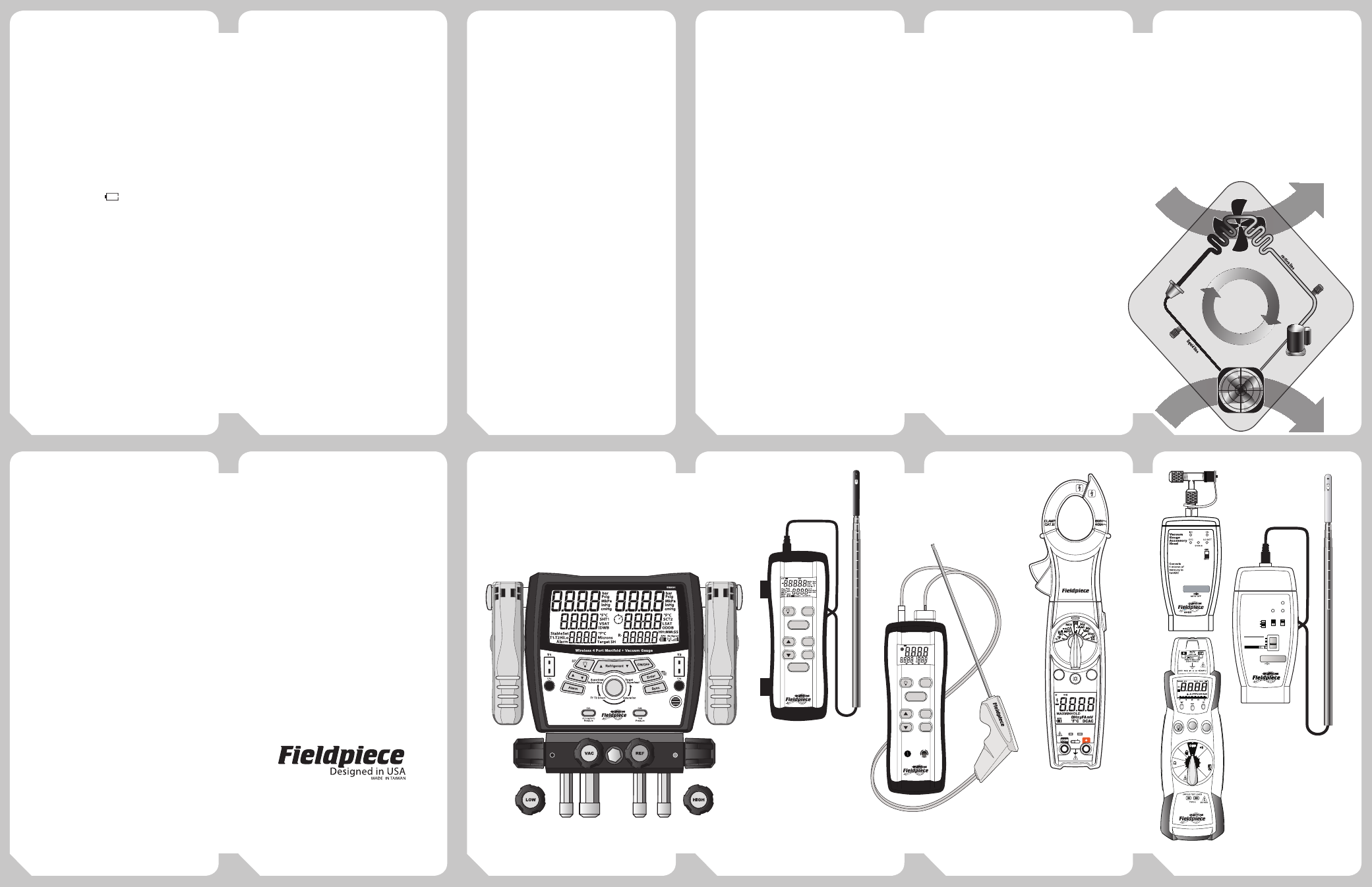
More Great
Products from
Fieldpiece
Relative Humidity:
Sensor type: Capacitance polymer film
Operating environment: 32°F to 131°F (0°C to 55°C)
Range: 0% to 100%RH
Accuracy: ±(2.5%) 10% to 90%RH
±(5%) <10%RH and >90%RH
Note: Above accuracies stated at 73.4°F (23°C).
Sensor response time: 60 seconds typical for 90% of
total range.
Sensor hysteresis: ±1%RH typical (Excursion of 10% to
90% to 10%RH)
Wireless:
Frequency range: 910MHz ~ 920MHz
FCC ID: VEARF915
Range: 100 feet
Minimum Wireless Range: 1 foot (30cm)
Error Codes
You may see an error code in TEET
or Target Delta T mode. Usually it
means probes are swapped or a bad
sensor (model RSDP2).
Err 01: Return wet bulb is higher than dry bulb.
Err 02: Return wet bulb is extremely low.
Err 03: Supply dry bulb is higher than return dry bulb.
Err 04: Return values are outside calculating range.
Err 05: Supply values are outside calculating range.
Err 06: Both the return and supply values are outside
calculating range.
(Err 04, 05, 06 supersedes Err 01, 02, 03)
EVAPORATOR
CONDENSER
THROTTLE
VALVE
COMPRESSOR
REFRIGERANT
FLOW
H
ig
h P
ress
ure Side
Low Press
ure
Sid
e
RETURN AIR
SUPPLY AIR
OUTDOOR AIR
HOT AIR
80
STA2
UNITS
CLEAR DATA
RECORD MODE
PRESS FOR
1 SECOND
In-Duct
Hot Wire
Anemometer
DUCT
ON/OFF
ENTER
HOLD
AVERAGE
MAX/MIN
AUTO-OFF
APO
MAXMIN HOLD SET
CO
2
EA
MAX
°F
%
%
°C
ENTER
AUTO-OFF
°F
°C
TEMP CAL
PRESS FOR
1 SECOND
SOX3
Combustion
Check
Excess Air,
%CO
2
and %O
2
Natural
Gas
Oil
#2
Propane Custom
EXHAUST
CLEAR
SET CUSTOM
ON/OFF
FUEL
MAX/MIN
MEASURE/HOLD
SC54
AUTO OFF
TRUE RMS
CAT III
600V
TEMP
K-TYPE
30V
MAX
O
F
F
SEL
HOLD
HOLD
MAX
MIN
MAX
MIN
SYNC
MAX
MIN
Ω
V
DC
V
AC
µA
DC
HZ
MFD
400m
400
Auto
4000m
1000
400
°C
°F
NCV
MAX
MIN
TRUE RMS
BACKLIGHT
NON-CONTACT VOLTAGE
HS36
AC
80
AAT3
In-Duct
Psychrometer
& Air Velocity
Head
ON
LO BATT
AVG
ENGLISH
ENGLISH METRIC
RH%
Ft/min
°F
RH%
M/s
°C
METRIC
DRY BULB
WET BULB
DEW POINT
AVG
NORMAL
AUTO OFF
In-Duct Hot-Wire
Anemometer
Model STA2
In-Duct
Psychrometer
and Air Velocity
Accessory Head
Model AAT3
Vacuum Gauge
Accessory Head
Model AVG2
True RMS Stick Meter
Model HS36
Swivel Clamp Meter
Model SC54
Combustion Check with AutoPump
Model SOX3
Wireless 4-Port Manifold
Model SMAN4