Safety information, Temp. calibration, Battery replacement – Fieldpiece LT17AW - Wireless Digital Multimeter User Manual
Page 2: Maintenance, Limited warranty, Obtaining service, Amps dc (adc) test leads, Amps ac (aac) test leads, Capacitance (mfd), Resistance (ω)
11
16
12
17
13
18
14
19
15
20
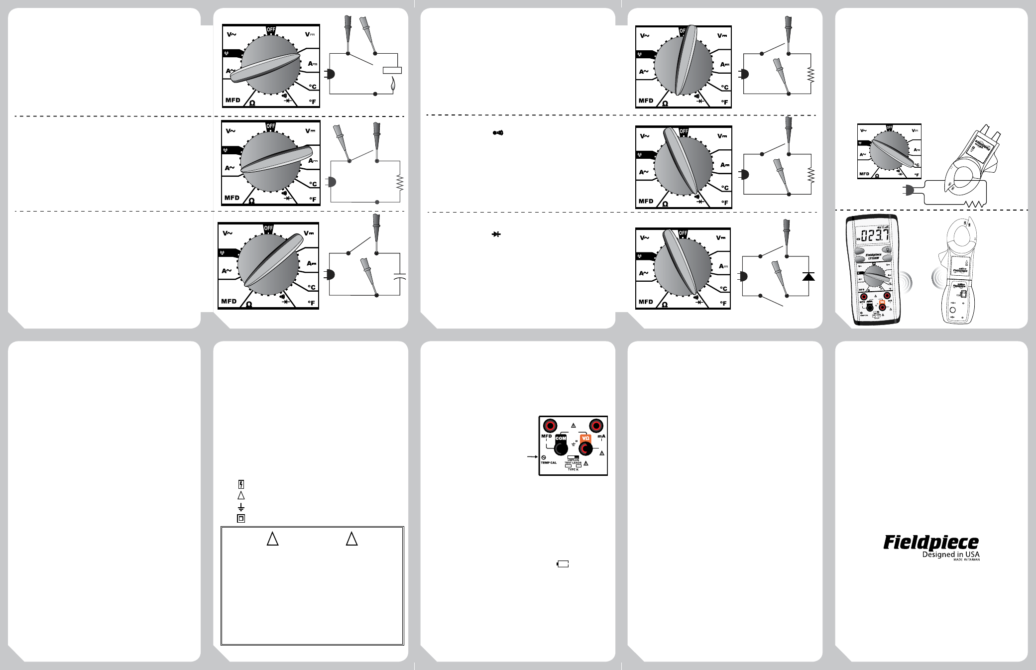
Amps DC (ADC) Test Leads
Microamps for flame rectifier diode test on a heater control.
Connect leads between flame sensor probe and control module and
turn heating unit on to read µA measurement. When the flame is on,
there should be a measurable µADC signal, typically under 10µADC.
Compare measurement to manufacture’s specification to determine
if replacement is necessary.
Ranges: 500µA, 50mA, 200mA Resolution: 0.1µA
Accuracy: ±(1.0% + 3) Voltage burden: 800mV
Input Protection: 0.25A / 500V fast blow ceramic fuse
Amps AC (AAC) Test Leads
Measure amps AC directly in the circuit. Measure small
amperages in fine circuitry.
Ranges: 500µA, 50mA, 200mA Resolution: 0.1µA
Accuracy: ±(1.5% + 6), 50Hz to 500Hz
Voltage burden: 800mV
Input Protection: 0.25A / 500V fast blow ceramic fuse
Capacitance (MFD)
Set to MFD to test motor start and run capacitors. Capacitors
are one of the most failure prone components in a HVAC/R system.
Discharge capacitor and disconnect from power and resistors
between terminals before testing.
Ranges: 20µF, 200µF, 2kµF Resolution: 0.01µF
Accuracy: ±(4% + 10)
Input Protection: 0.25 / 500V fast blow ceramic fuse
Resistance (Ω)
Used for “ohming out” a motor. 0.1Ω resolution is necessary to
test the resistance between the motor poles because the values are
typically very low.
Ranges: 200Ω, 2kΩ, 200kΩ, 20MΩ
Resolution: 0.1Ω Overload Protection: 500VDC/VAC rms
Accuracy: ±(1.0% + 4) 200Ω to 200kΩ, ±(2% + 4) 20MΩ range
Open Circuits Volts: 0.3VDC typical, (2.5VDC on 200Ω range)
Overload Protection: 500VDC or AC rms
Continuity (
O
F
F
MFD
NCV
V
AC
V
DC
A
AC
Hz
Hz
%
°C
°F
SC56
AUTO OFF
TRUE RMS
CAT III
600V
TEMP
K-TYPE
30V
MAX
SEL
HOLD
INRUSH
)
Use the continuity feature to test if a circuit is open or closed.
Use this feature to check fuses as well. A steady “beep” to indicate
continuity in a circuit.
Response time: 100ms
Audible beep: <100Ω
Overload Protection: 500VDC/VACrms
Diode Test (
O
F
F
MFD
NCV
V
AC
V
DC
A
AC
Hz
Hz
%
°C
°F
SC56
AUTO OFF
TRUE RMS
CAT III
600V
TEMP
K-TYPE
30V
MAX
SEL
HOLD
INRUSH
)
Test diodes for proper forward and reversed-biased functions.
Test current: 0.5mA (Approx.) Accuracy: ±(1.5% + 3)
Open Circuit Volts: 2.5VDC typical
Overload Protection: 500VDC/VACrms
500
600
600
50
5000m
500m
500µ
50m
200m
200m
500m
5000m
50m
50500
500µ
500
750
500
1400
200
2
K
200
20
M
2
K
200
K
20
RECV
500
600
600
50
5000m
500m
500µ
50m
200m
200m
500m
5000m
50m
50500
500µ
500
750
500
1400
200
2
K
200
20
M
2
K
200
K
20
RECV
500
600
600
50
5000m
500m
500µ
50m
200m
200m
500m
5000m
50m
50500
500µ
500
750
500
1400
200
2
K
200
20
M
2
K
200
K
20
RECV
Amps AC (AAC) Through the Clamp
Test any isolated power line. Turn the dial to 500mVAC switch
position. Plug tests leads into COM and VΩ ports on meter. Remove
probe tips from test leads and plug leads into ACH4 banana plugs.
Range: 1-400A Resolution: 0.1A Frequency: 50-60Hz
Jaw Opening: 1.2in (30 mm)
Accuracy: ±(2.7% + 8) on 1-20AAC
±(3.7% + 9) on 20-100AAC
±(4.7% + 11) on 100-400AAC
Note: Above stated accuracies are a system accuracy combining both
the ACH4 and LT17AW accuracies.
Safety Information
• Never ground yourself when taking electrical
measurements. Do not touch exposed metal
pipes, outlets, fixtures, etc., which might be
at ground potential, while taking measure-
ments. Keep your body isolated from ground
by using dry clothing, rubber shoes, rubber
mats, or any approved insulating material.
• Disconnect the test leads before opening the
case. Inspect the test leads for damage to the
insulation or exposed wire. Replace if suspect.
Keep your fingers behind the finger guards
on the probes while taking measurements.
• When disconnecting from a circuit, disconnect
the “RED” lead first, then the common “BLACK”
lead. Use one handed testing when possible.
Work with others.
• Turn off power to the circuit under test before
cutting, unsoldering, or breaking the circuit.
• Do not measure resistance (ohms) when circuit
is powered. Isolate load by disconnecting
from circuit.
• Disconnect the meter from the circuit before
turning any inductor off, including motors,
transformers, and solenoids. High voltage
transients can damage the meter beyond
repair. Do not use during electrical storms.
• Do not apply more than rated voltages between
input and ground.
• Isolate capacitors from system and discharge
them safely before testing.
• Temp switch to prevent leaving thermocouple
plugged in while measuring voltage.
All voltage tests: All voltage ranges will with-
stand up to 600V. Do not apply more than
600VDC or AC rms.
Symbols used:
Caution, risk of electric shock
Caution, refer to manual.
Ground
Double insulation
Temp. Calibration
For accuracies of ±1°F, calibrate to a known
temperature. A glass of stabilized ice water
is very close to 32°F (0°C) and is usually very
convenient but any known temperature can
be used.
1. Select the 500°F range.
2. Plug thermocouple to be
calibrated into the K-type jack.
4. Stabilize a large cup of ice water.
Stir the ice with the water until
temperature stays at 32°F (0°C).
5. Immerse the thermocouple probe and let it stabilize. Keep stirring
to prevent micro-environments.
6. Use a small screwdriver to adjust calibration pot to the lower left
of the COM port as close to 32°F as you would like.
Battery Replacement
The battery in the LT17AW must be replaced
when the lower left battery icon (
) is empty.
The LT17AW will display "bAtt" on the LCD
accompanied by a continuous beep. The
meter will turn off in 5 seconds and no further
measurement will be allowed until the battery
is replaced.
Maintenance
Clean the exterior with a dry cloth. Do not
use liquid.
Limited Warranty
In the USA, this meter is warranted against
defects in material or workmanship for one year
from date of purchase. Fieldpiece will replace or
repair the defective unit, at its option, subject to
verification of the defect.
This warranty does not apply to defects
resulting from abuse, neglect, accident,
unauthorized repair, alteration, or unreasonable
use of the instrument.
Any implied warranties arising from the sale of
a Fieldpiece product, including but not limited
to implied warranties of merchantability and
fitness for a particular purpose, are limited to
the above. Fieldpiece shall not be liable for loss
of use of the instrument or other incidental or
consequential damages, expenses, or economic
loss, or for any claim of such damage, expenses,
or economic loss.
State laws vary. The above limitations or
exclusions may not apply to you.
Obtaining Service
In the USA, call Fieldpiece Instruments for
one-price-fix-all out of warranty service pricing.
Send check or money order for the amount
quoted. Send the meter freight prepaid to
Fieldpiece Instruments. Send proof of date and
location of purchase for in-warranty service.
The meter will be repaired or replaced, at the
option of Fieldpiece, and returned via least
cost transportation. Outside of the USA, please
visit www.fieldpiece.com for service contact
information.
www.fieldpiece.com
© Fieldpiece Instruments, Inc 2011; v07
COM
VΩ
CA
T .III
300V
400A
CLAM
P
ACH4
AC Cur
rent
Clamp
1AAC / 1mV
AC
400AAC MAX
!
500
600
600
50
5000m
500m
500µ
50m
200m
200m
500m
5000m
50m
50500
500µ
500
750
500
1400
200
2
K
200
20
M
2
K
200
K
20
RECV
FUSED
200
m
A
MAX
FUSED
30V
MAX
CAT.III
MAX
600V
15 SEC FOR
500
m
V
RANGE
!
WARNINGS
!
DISCONNECT AND UNPLUG TEST LEADS before opening case.
DO NOT APPLY VOLTAGE greater than 30VAC or 60VDC to the
thermocouple or the jacks when the rotary dial is on °F. (Use
only k-type thermocouples)
REMOVE THE THERMOCOUPLE when taking voltage measurements.
DISCONNECT TEST LEADS when measuring temperature.
DO NOT APPLY VOLTAGE TO THE JACKS when the rotary dial is on
microamps. Even low voltages can cause a current overload and
potentially harm the meter.
!
500
600
600
50
5000m
500m
500µ
50m
200m
200m
500m
5000m
50m
50500
500µ
500
750
500
1400
200
2
K
200
20
M
2
K
200
K
20
RECV
500
600
600
50
5000m
500m
500µ
50m
200m
200m
500m
5000m
50m
50500
500µ
500
750
500
1400
200
2
K
200
20
M
2
K
200
K
20
RECV
Discharge Cap First!
500
600
600
50
5000m
500m
500µ
50m
200m
200m
500m
5000m
50m
50500
500µ
500
750
500
1400
200
2
K
200
20
M
2
K
200
K
20
RECV
CAT.III
300V
400A
CLAMP
ACH4
AC Current
Clamp
1AAC / 1mVAC
400AAC MAX
!
ET2W
LO BATT
SEND
RECEIVE
ON
AC
DC
Wireless
Transmitter
SYNC
FUSED
200
m
A
MAX
FUSED
30V
MAX
WIRELESS
ENABLED
MAX/MIN
SYNC
HOLD
CAT.III
MAX
600V
15 SEC FOR 500
m
V
RANGE
AUTO-OFF
500
600
600
50
5000m
500m
500µ
50m
200m
200m
500m
5000m
50m
50500
500µ
500
750
500
1400
200
2
K
200
20
M
2
K
200
K
20
RECV
ET2W w/ ACH4
transmitting
wirelessly to
LT17AW