Diagnostic tests, Wireless return wet bulb for target superheat, Measuring accurate airflow – Fieldpiece AAT3 - Hot-wire Anemometer & Psychrometer Accessory Head User Manual
Page 2: Proper measurement points for round ducts, Target evaporator exit temp with the hvacguide
13
15
18
14
17
16
19
21
24
20
23
22
Diagnostic Tests
Wireless Return Wet Bulb
for Target Superheat
The AAT3 with a wireless transmitter
(ET2W, EH4W, or LT17AW) allows to
you monitor the return wet bulb while
you are at the condensor. Send this
real-time WB measurement wirelessly
to the INPUT FORM of the HVAC Guide
(HG3) to calculate a real-time target
superheat.
1. Sync your transmitter with AAT3 to
the Return WB INPUT line in Super-
heat Test of the HG3.
2. Punch or drill a small 3/8" hole in
the return plenum to insert AAT3
probe. Press ENTER on the HG3 to
lock reading.
3. Input an outdoor dry bulb manually
or with an ATH4 at the consdensor
into the OD Dry Bulb INPUT line in
the Superheat Test of the HG3.
4. Press OUTPUT on HG3 to see your
target superheat calculations.
return and selecting the appropriate
switch position on the AAT3. Press
ENTER to lock reading.
4. In the INPUT FORM, highlight Sup-
ply DB. Press ENTER to measure
air temperature coming out of the
evaporator. Punch or drill a small
3/8" hole in the supply plenum and
insert ARH5 wand in the center of
the plenum to take measurement.
Press ENTER to lock reading.
5. Press OUTPUT to view results.
Measuring Accurate
Airflow
Find a Suitable Location
for a Traverse
1. The cross sectional area at, before and after the
traverse location should be a either rectangular
or round.
2. Make sure you have sufficient access around
the traverse location so that the duct may be
traversed at multiple angles.
3. The traverse location should be chosen so as to
minimize the effects of leaks in the portion of
the system between the fan and the traverse
location.
4. The traverse location should be located far
enough downstream of the fan to allow the
airflow to come to a uniform distribution.
To determine an effective length, assume a
minimum of 2.5 duct diameters for 2500 ft/
min or less and add 1 duct diameter for each
additional 1000 ft/min measured. (For a
rectangular duct the equivalent diameter can
be calculated as D=√(4hw/π) where “h” is the
height of the duct and “w” is the width.)
5. Locations directly downstream from
obstructions, bends or sudden changes in the
duct are not good locations for a traverse.
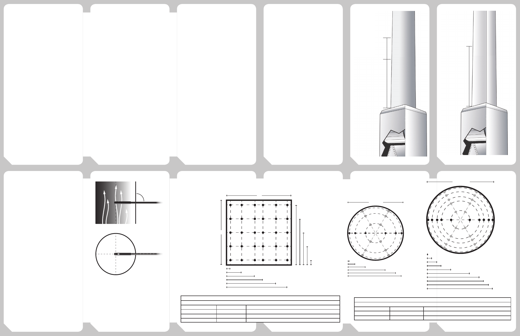
Execute the Traverse
1. Determine the appropriate measurement
points by measuring either the diameter of
the duct or the width and height. Then use the
appropriate table (See table 1 and 2) to calculate
the insertion depth where each of the point
measurements should be recorded.
2. Set the average switch on the AAT3 to AVG to
display a 16 second running average.
3. Insert the probe tip of the AAT3 into the duct
and use the flat edges of the probe to align the
sensor with the airflow direction. Check that
the direction of airflow is at 90° to the probe by
making sure that the probe is at a right angle to
the side of the duct.
4. Use the laser etched ruler on the side of the
probe probe to measure the insertion depth and
find the locations you determined in step 1.
5. Record a point measurement (Either manually or
by using the Fieldpiece HG3, or DL3) at each of
the locations determined in step 1.
6. Use the recorded velocity measuremtents
to calculate the airflow by first detemining
the average velocity of the traverse and then
multiplying by the free area of the duct.
Proper Measurement
Points for Rectangular/
Square Ducts
TABLE 1
Traverse locations using log-Tchebycheff rule in a rectangular duct
Length of Side
# of Traverse Lines
Distance from Inner Wall in % of Length of Side
< 30 in (76 cm)
5
7.4%, 28.8%, 50%, 71.2%, 92.6%
30-63in (76-160cm)
6
6.1%, 23.5%, 43.7%, 56.3%, 76.5%, 93.9%
>63in (160cm)
7
5.3%, 20.3%, 36.6%, 50%, 63.4%, 79.9%, 94.7%
Proper Measurement
Points for Round Ducts
TABLE 2
Log linear rule for traverse points on two diameter for a round duct
Diameter
# of points per diameter
Distance from inner wall in % of diameter
<10in (25.4cm)
6
3.2%, 13.5%, 32.1%, 67.9%, 86.5%, 96.8%
≥ 10in (25.4cm)
10
1.9%, 7.7%, 15.3%, 21.7%, 36.1%, 63.9%
Target Evaporator Exit
Temp with the HVACGuide
The AAT3 with Fieldpiece HVAC
Guide, allows you to easily perform
a Target Evaporator Exit Temperature
(TEET ) test to determine if the
evaporator is getting the optimum
airflow.
1. Slide AAT3 onto the top of the HVAC
Guide. Select TEET switch position.
2. In the INPUT FORM, highlight Return
DB. Set the AAT3 to the Temperature
switch position and select dry bulb.
Press ENTER to measure air tem-
perature going into the evaporator
Drill a small 3/8" hole in the return
plenum and insert the AAT3 probe.
Press ENTER to lock reading. Take
measurements as close to the air
handler as possible. Seal any holes
before leaving the jobsite.
3. In the INPUT FORM, highlight Re-
turn WB. Press ENTER to measure
wet bulb temperature going into
the evaporator by inserting AAT3
probe through the same hole at the
90°
D
(<10”)
D
(>10”)
W
H
0.032D
0.135D
0.321D
0.679D
0.865D
0.968D
0.019D
0.077D
0.153D
0.217D
0.361D
0.639D
0.061W
0.235W
0.437W
0.563W
0.765W
0.939W
0.926H
0.712H
0.500H
0.288H
0.074H
0.783D
0.847D
0.923D
0.981D
90°
D
(<10”)
D
(>10”)
W
H
0.032D
0.135D
0.321D
0.679D
0.865D
0.968D
0.019D
0.077D
0.153D
0.217D
0.361D
0.639D
0.061W
0.235W
0.437W
0.563W
0.765W
0.939W
0.926H
0.712H
0.500H
0.288H
0.074H
0.783D
0.847D
0.923D
0.981D
90°
D
(<10”)
D
(>10”)
W
H
0.032D
0.135D
0.321D
0.679D
0.865D
0.968D
0.019D
0.077D
0.153D
0.217D
0.361D
0.639D
0.061W
0.235W
0.437W
0.563W
0.765W
0.939W
0.926H
0.712H
0.500H
0.288H
0.074H
0.783D
0.847D
0.923D
0.981D
90°
90
85
80
90°
90
85
80
2.5 D
1 D
Traverse here if
velocity is 2500ft/min
Traverse here if
velocity is 3500ft/min
FAN
Ex. 8” round duct
D=8”
2.5D=20“
2.5D+1D=28”
*Not to Scale
2.5 D
Ex. 24”x 8” duct
H=24
W=8
D=√(4HW/π)
D=16” (approx.)
2.5D= 40” (approx.)
Traverse here if
velocity is
2500ft/min
*Not to Scale