Dakota Digital 3X User Manual
Page 31
MAN 650067:G
31
Symptom
Possible Problem
Solution
-----------------------------------------------------------------------------------------------------------------------------------
The Check Engine
The Engine Control Module
Connect a bulb with one wire to
indicator stays on
(ECM) needs to see the
keyed power and the other to
all of the time.
load of a light connected to it.
the CHECK ENG terminal.
The Function switches
The push-button switches are
Momentary push-button or toggle
do not operate
not connected to the control
switches must be connected to
properly.
box.
the SW1 and SW2 terminals
as described in the manual.
The wrong type of switch is
The switch terminal connected
being used.
to the control box should
normally be open. When the
the switch is activated, the
terminal should make contact
to ground.
The display system starts
SW2 terminal is constantly
Disconnect or replace the
up in the demonstration
connected to ground.
SW2 switch.
mode and remains in it.
Clock Instructions
For VFD3X systems with an ODYR-16 clock with day/date and temp built in
Features:
•
12 hour format with AM/PM display.
•
Day of Week and Date of Month display.
•
Outside Temperature display.
•
Night dimming.
•
High Visibility VFD display for sunlight readability.
Operation:
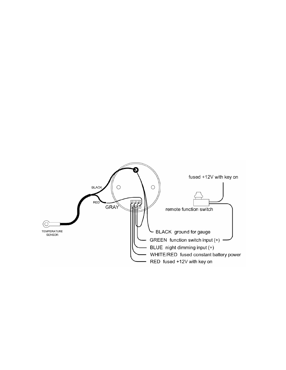
The white/red wire should be connected to a constant 12 volt feed to keep the time. The red wire should
be connected to a 12 volt accessory feed. The black wire provides the gauge ground. Connect the ring terminal
from the black wire to a screw at the top rear of the case. Attach the loose end of the black wire to a main vehicle
ground and also the temp sensor black wire. When the blue wire has 12 volts, it will dim the display for night
viewing. The gray wire attaches to the temp sensor red wire. The green wire will be used with a remote mount
switch. The remote switch should apply power to the green wire when pressed.