Assembly – DR Power 3-Point Hitch Top-Discharge User Manual
Page 8
8
SECTION II - ASSEMBLY & INSTALLATION
PACKAGE CONTENTS
SKID
PARTS BOX
BOLT BAG
CHIPPER
PTO DRIVE SHAFT
1 EA – UPPER SPACER – 1 625”
DISCHARGE CHUTE
CHIPPER HOPPER
2 EA – LOWER SPACER – 1.6”
PARTS BOX
SWIVEL TOP
1 EA – UPPER MOUNT PIN
DEFLECTOR
4 EA – 3/16” HAIR PIN
OWNER’S MANUAL
1 EA – ¼” X ¼” X 1 ½” KEY
WARRANTY CARD
7 EA – 5/16-18 X ¾” CARRIAGE BOLT
SAFETY GLASSES
4 EA – 5/16 FLAT WASHERS
BOLT BAG
8 EA – 5/16-18 NYLOCK NUT
KNIFE GAUGE
2 EA – 3/8-16 X 3/8” SET SCREW
3 EA – 3/8 USS FLATWASHERS
1 EA – LOCKING KNOB
2 EA – 5/16-18 X ¾” HHCS
TOOLS REQUIRED FOR ASSEMBLY & INSTALLATION
• ½” Box wrench
• ½” Socket and ratchet driver
ASSEMBLY
STEP I – UNPACKING AND CHECKING CONTENTS
• Remove the all items from the crate.
• After unpacking the crate, compare the contents with the list above.
• If any parts are missing, contact Country Home Products at 800-376-9637.
• Assembly should be done on a clean, level surface.
• Do not discard your packaging material until you are fully satisfied with your new DR Chipper.
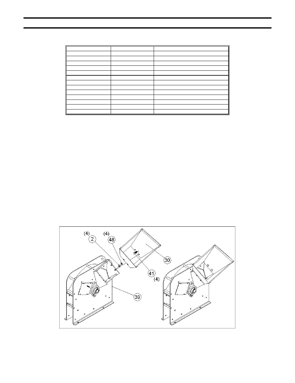
STEP II – ASSEMBLING THE CHIPPER HOPPER
• Assemble chipper hopper (#30, pg 25) to the basic machine (#39, pg 25) using four each 5/16”-18 x ¾”
carriage bolts (#41, pg 25), 5/16”-18 nylock nuts (#2, pg 25) and 5/16” flatwashers (#48, pg 25) from the
bolt bag. Put head of bolt inside hopper with threads sticking out. Tighten all hardware with a ½” wrench.