Installation of base post, Concrete pad for 3.7m antenna – DH Satellite 60 Heavy Duty Polar/Powered Dec User Manual
Page 4
INSTALLATION OF BASE POST
With this polar mount you have a choice of using the factory TX base stand (page 5) or
using a base post. If you are using a post, please be sure to check with an engineer to
determine the reinforcing required on this single post. DH Satellite will not engineer post
designs. When placing your post in the concrete be sure it is plumb. The following chart shows
how much of the post should be out of the ground for the different size antennas.
3.0M antenna. . . . . . . . . . . . . . . . . 5’ 0” out of ground
3.3M – 3.7M antenna. . . . . . . . . . 5’ 6” out of ground
3.9M – 4.2M antenna. . . . . . . . . . 6’ 0” out of ground
4.5M – 5.0M antenna. . . . . . . . . . 7’ 0” out of ground
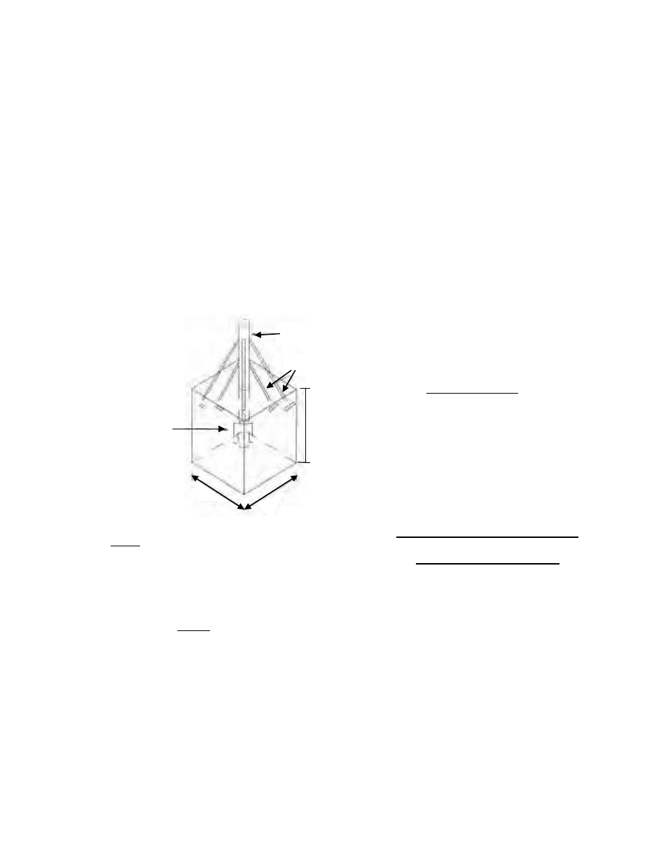
5” I.D. Post (Post must be plumb)
Weldments into concrete
2” angle approx. 16” long
POST DESIGN CRITERIA
Wind speed:
100 mph max. 5” schedule 80
125 mph max. 5” schedule 120
CONCRETE PAD FOR
3.7M ANTENNA
NOTES:
•
5 #3 Rebar used in footings
•
Rebar distributed evenly in two directions
•
Center of rebar should be min. of 2” above bottom of pad
•
Outside of bars should be 3” from edge of footings
NOTES:
•
Pad must extend below frost depth
•
Dimensions for concrete may vary depending on soil types and wind conditions, check with local
engineer
•
Post must be 5’6” min. out of pad
•
Post must have weldments on side to prevent post from turning in wind
•
Post must be clear 20” from top
•
If possible triangulate from post to concrete with tube or angle as in sketch above
•
Not to any scale
3’0” or below frost
Page 4
5’9”
5’9”