Venus 1500 display receiver, Controller board and mdc board – Daktronics AB-1010 User Manual
Page 28
Maintenance &
4-4
eiver
4.9
Venus 1500 Display Rec
Reference Drawings:
2-Board V1500 Display Receiver Wiring Layout .................................. Drawing A-138543
Assy; V1500 Display Recvr, RS232/422.............................................. Drawing B-130244
Assy; V1500 Display Recvr, Modem ................................................... Drawing B-130246
r Optic .............................................. Drawing B-130247
Sho
....................... Drawing B-149589
................................... Drawing B-149590
The
signal from the Venus 1500 controller which routes signal
to e
etc.,
in it
r the
cation of the V15DR.
The
nts, including a controller board, a fan and two Current Loop
Out
To rem
play on Drawings B-149589 and B-149590.
pe
Remove the screw on the bottom middle of the V15DR cover and lift off the cover from the
4.
ctors found on the controller board.
As
Schematic, V15DR, 1500 .................................................................... Drawing B-140468
p Drawing, 7**-24 IOC-L ........................................
sy; V1500 Display Recvr, Fibe
Shop
Drawing,
16**-24 IOC-L ..........................
Venus 1500 Display Receiver receives
ach display driver (8 pixels/16 pixels). The Venus 1500 controller stores messages, schedules,
s memory. The controller is also addressable. Refer to Drawings B-149589 and B-149590 fo
lo
V15DR consists of several compone
put cards.
ove a V15DR component from the display:
1. Locate the V15DR placement within the dis
2. O
n the display according to Section 4.4.
3.
enclosure.
Individual parts in the V15DR may be removed from the enclosure by disconnecting the power
and signal connectors and removing the screws and lifting the components from the standoffs.
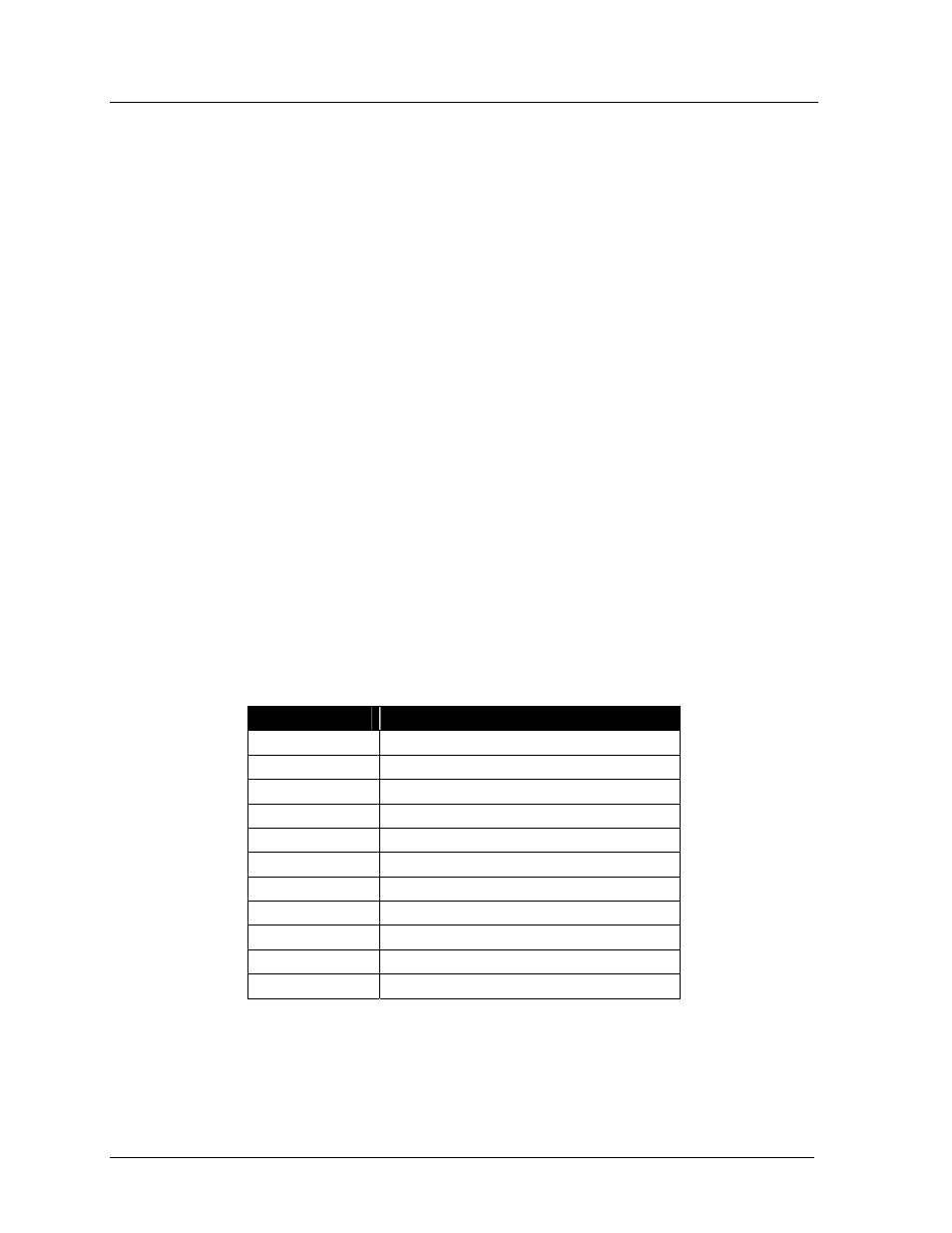
Controller Board and MDC Board
The table below lists the functions of the conne
Connector
Function
J1
RS232 In – COM1
TB1
RS232 In – COM1
TB2
RS422 In – COM1
TB3
RS422 Out – COM1
TB4
RS232 In – COM2
TB5
RS422 In – COM2
TB6
RS422 Out – COM 2
J2
10 VAC Input
J3 N/A
TB11, TB12
Current Loop Out
J11, J12, J13
Output to Current Loop Output cards
On the controller board are a number of diagnostic LEDs. The LEDs and their respec
functions and operations are listed in the following table.
tive
Troubleshooting