Electrical service requirements, Panel board assignments – Daktronics AB-1010 User Manual
Page 20
Electrical Installation
3-4
A disconnect that opens all of the ungrounded phase conductors should be used.
nd conductors should be bonded in the display panelboard.
Refer to Error! Reference source not found. for installation details.
.4
· Connect the grounding electrode cable at the local disconnect, never at the display
panelboard.
·
· The neutral and the grou
3
Electrical Service Requirements
R ference Drawings:
e
System Riser Diagram, RS232 Incandescent Displays ....................... Drawing A-148870
Power Specs, Sunspot ........................................................................ Drawing A-148967
to the
ents. Note: All electrical service requirements listed in
these tables are calculated based on the maximum wattage lamp offered for each display size. The
installer is to supply an external mounted fused main disconnect(s) and wire to the panel board. The
installer must field punch a hole or holes in the cabinet at the appropriate location for power cable
entrance to panel board.
The panel board is provided in the master display cabinet. Single panel boards are always located to
the left of the right-most lamp driver enclosure assembly. When a second panel board is provided, it
will be found to the left of the first panel board (between two lamp driver enclosure assemblies).
When a second panel board is provided, two externally mounted fused main disconnects are required.
Refer to the tables below for the number of disconnects required for your particular application.
Note:
the panel board(s) but are not hooked up. They must be
nnected when the main power is hooked up to the panel board. Refer to Drawing A-74902 for the
oper connections.
Two Wire/Three Wire/ Two Surge Arresters (A-1129) ........................... Drawing A-74902
System Riser Diagram, RS422 Incandescent Displays ....................... Drawing A-148859
System Riser Diagram; Fiber Incandescent Displays .......................... Drawing A-148878
System Riser Diagram; Modem Incandescent Displays ...................... Drawing A-148884
The panel board is provided internally for display power distribution to the driver circuits. Refer
tables below for electrical service requirem
Surge Suppressors are installed in
co
pr
3.5
Panel Board Assignments
Reference Drawings:
Lamp Driver, 16 Column w/ Fan ............................................................ Drawing A-37070
Drawin
: Two
or f
illustrated in the following set of tables) where A indicates the driver/module number.
Thi
s.
Not
g A-37070 illustrates the electrical distribution from the panel board to the drivers. Note
our breakers feed each driver. All power wires are labeled with a number in the format A (as
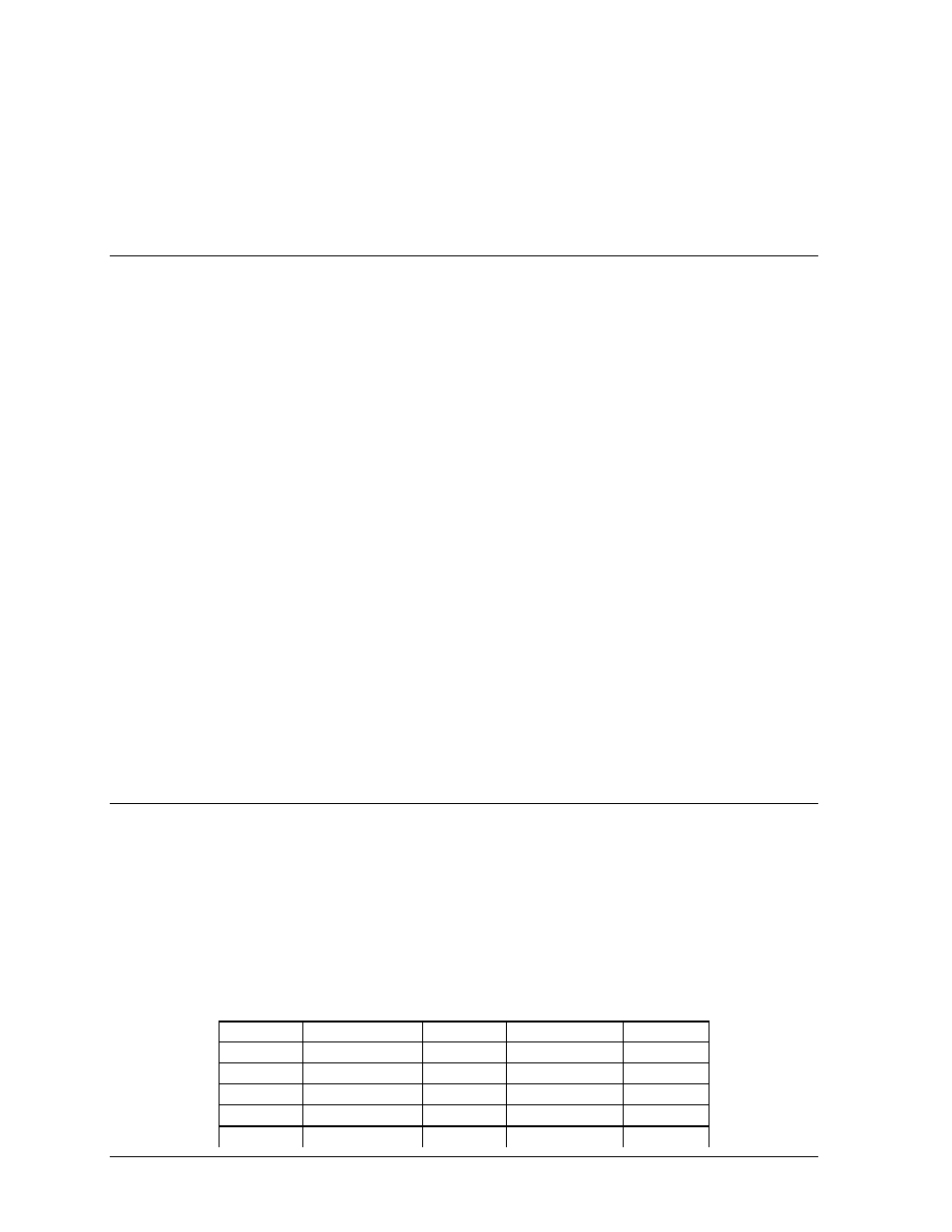
s table is for a 16x64 single face display. It has a 125-amp panel board and uses 16 of 20 position
e that two breakers feed each driver.
Breaker
Wire
Driver
Wire
Breaker
1
A101 (Black)
A101
A101 (Red)
2
3
A102 (Black)
A102
A102 (Red)
4
5
A103 (Black)
A103
A103 (Red)
6
7
A104 (Black)
A104
A104 (Red)
8
9
A201 (Black)
A201
A201 (Red)
10