Electrical installation, Common connectors, Stal – Daktronics AB-1010 User Manual
Page 17: Figure 14: in
Section 3: Electrical Installation
3.1 Common
Connectors
nnectors for power and signal termination. Take special
g any connector so as not to damage the connector, the cable or the circuit board.
ack, do not pull on the wire or cable; pull on the jack
e the connector.
wing information presents some common connectors that may be encountered during display
aintenance. Not all of these connectors are found in every display.
s):
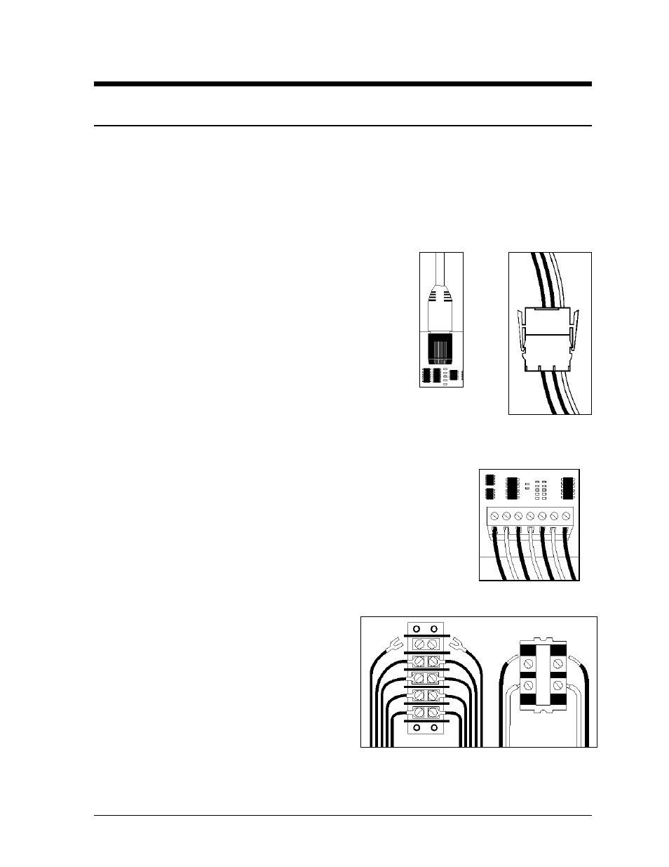
RJ11 connectors, as seen in Figure 9, are similar to the
ound in homes and are used on the
ny foreign matter that may cause
signal problems. In addition, apply a generous amount of
from corrosion. Both the Deoxit and the Cailube can be
display. Refer to the replacement parts list in Section 4 if you need additional
The
n-Lok connectors found in this display are white and come in a
ate-n-Lok connectors
rs are often used for
ate-n-Lok connector.
lastics locking clasps of
re usually green and
are often used for signal termination on circuit
t a wire, push the bare
wire into the connector and turn the above screw
ct internal power and signal wires to wires of the same type
crimped to the ends of the wire. Power wires need to have one-half inch of insulation
This display uses many different types of co
care when disengagin
When pulling a connector plug from a j
itself. Pulling on the wires may damag
The follo
m
1. Phone Jacks (RJ11 Connector
Figure 10:
Mate-n-Lok
Connector
Electrical Installation
3-1
telephone connectors f
ends of cable. In order to remove this plug from the jack,
depress the small clip on the underside of the plug.
Before replacing an RJ11 connector, spray it with Deoxit
™
contact cleaner to remove a
Cailube
™
protector paste to the plug before inserting it into
the jack. This paste will protect both the plug and the jack
Figure 9:
RJ11
Connector
found in the tool kit accessories package included with this
quantities of either.
Figure 11: Phoenix-
Style Connector
2. Mate-n-Lok
J
Connectors:
Mate-
variety of sizes. Circuit boards often used 9-pin M
while four-pin connectors and two-pin connecto
power connection. Figure 10 shows a four-pin M
To remove the plug form the jack, squeeze the p
the side of the plug and pull it from the jack.
3. Phoenix
J
-Style Connectors:
Phoenix-style connectors a
boards. Refer to Figure 11. Strip one-quarter
inch of insulation from the wire prior to
termination. To remove a wire, turn the above
screw counter-clockwise to loose the connectors
grip on the wire. To inser
clockwise to lock the wire into place.
5. Termination
Blocks:
Termination blocks usually conne
Figure 12: Termination Blocks (left: signal; right: power)
coming into the display from an external source. Most signal wires will come with forked
connectors