Before installation, Power, Grounding – Daktronics AB-1010 User Manual
Page 18: Igna, Roller board -5, L converters
stripped from the end of the wire prior to termination. Tighten all screws firmly to ensure a good
electrical connection. Refer to Figure 12.
Electrical Installation
3-2
3.2 Before
Installation
eference Drawings:
System Riser Diagram, RS422 Incandescent Displays ....................... Drawing A-148859
ys
ing A-148870
System Riser Diagram; Fiber Incandescent Displays .......................... Drawing A-148878
-L ............................................................... Drawing B-149589
Shop
Drawing,
16**-24 IOC-L ............................................................. Drawing B-149590
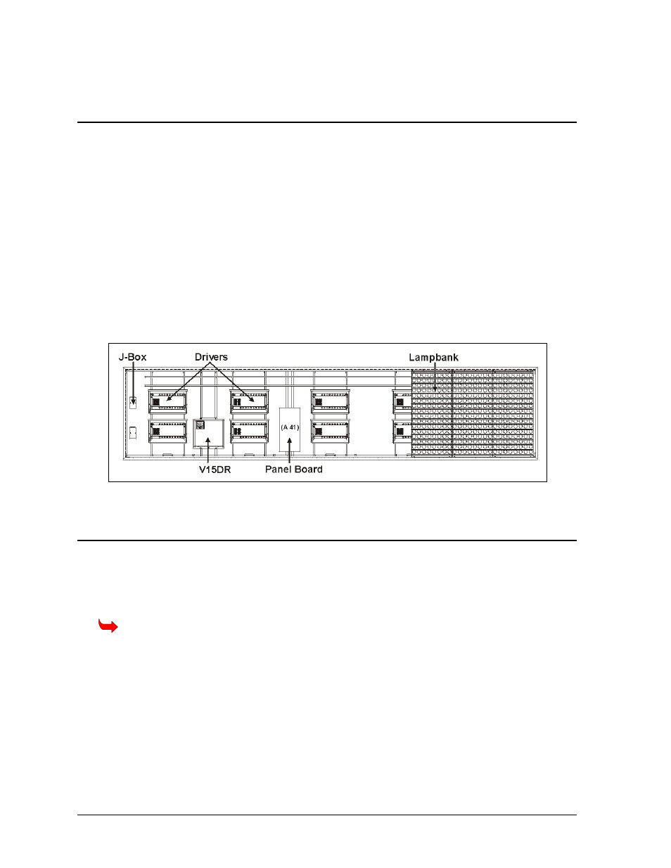
and power to the display, locate the necessary display parts where connections
ill need to be made, including the panel board, the V15DR, the Junction Box (J-Box) and the drivers.
3.3 Power
R
S
tem Riser Diagram, RS232 Incandescent Displays ....................... Draw
System Riser Diagram; Modem Incandescent Displays ...................... Drawing A-148884
Shop Drawing, 7**-24 IOC
Before installing signal
w
Refer to Figure 13 for a typical layout of the electrical components within a 16x64 matrix display.
Electrical component locations may vary with display size. Refer to DrawingsB-149590 and B-
149589 for component layout.
Figure 13: Component Locations
Proper power installation is imperative for proper display operation. The following sub-sections give
details of display power installation.
Grounding
Displays MUST be grounded according to the provisions outlined in Article 250 of the
National Electrical Code
®
. Daktronics recommends a resistance to ground of 10 ohms or less.
The display system must be connected to earth-ground. Proper grounding is necessary for reliable
equipment operation. It also protects the equipment from damaging electrical disturbances and
lightning. The display must be properly grounded or the warranty will be void.
The material of an earth-ground electrode differs from region to region and from conditions
present at the site. Consult the National Electrical Code and any local electrical codes that may
apply. The support structure of the display cannot be used as an earth-ground electrode. The
support is generally embedded in concrete, and if in earth, the steel is either primed or it corrodes,
making it a poor ground.