Display mounting, Ure 1, Nix-style connector -1 – Daktronics AB-1010 User Manual
Page 15
Introduction
2-3
xample) method of lifting
t the eyebolts directly to
e central lifting point; doing so may cause the eyebolts to fail.
ign by the eyebolts.
nd the rubber
ealing washer that was removed from the
Figure 7 illustrates both the correct (left example) and the incorrect (right e
a sign. Lift the sign as shown on the left, with the lifting bar. Do not connec
th
Use every lifting point provided!
Do not attempt to permanently support the
Figure 7: Lifting the Sign
s
If removing an eyebolt from the display,
plug the hole with a bolt a
s
eyebolt.
2.6 Display
Mounting
Reference Drawings:
Shop Drawing, 7**-24 IOC-L................................................................ Drawing B-149589
g B-149590
he
re the installation adequately meets local codes and
le for the mounting method and the hardware.
will not give way at any unsupported points after the sign is mounted.
ounted to the back of the display and another set is
clips are joined using ½
O Grade-5 bolts; refer to
qualified structural engineer.
The
review the number of attachment points needed and
onal and
cal codes. Daktronics recommends using all clip
gles as attachment points.
1. Carefully uncrate the sign. Look each side of the sign over for damage during shipping. If you find
damage, call Daktronics Customer Service at the numbers listed in Section 4.14.
2. Weld or use ½
O Grade-5 bolts and hardware to secure the mounting clips to the support structure
as shown in the Shop Drawing.
3. Following the guidelines described in Section 2.4, lift the sign into position on the support
structure.
Shop
Drawing,
16**-24 IOC-L.............................................................. Drawin
The method used to mount signs varies greatly from location to location; as such, this manual covers
only general mounting topics.
It is t
installer’s responsibility to ensu
standards. The installer is also responsib
Before beginning the installation process, verify the following items.
·
The mounting structure will provide a straight and square frame for the sign. Height variation in
any four-foot horizontal section may not exceed ¼- inch.
·
The mounting structure
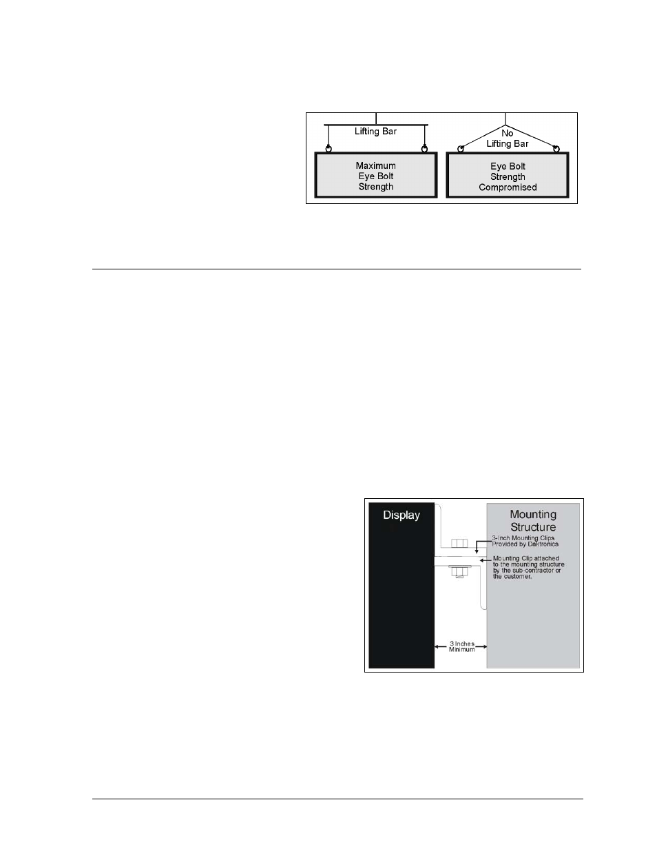
Figure 8: Mounting Example
The back of the sign uses 3x3 mounting clips at the
locations shown in the Shop Drawings; one set is
m
mounted to the structure. The two sets of mounting
Fi ure 8. These clips assist in mounting the sign.
Remember to have all mounted signs inspected by a
customer must have a qualified structural engineer
the wall structure to ensure both meet all nati
lo
an