Daktronics AF-3065-34-RGB User Manual
Page 40
Loop-Back Test: To perform a loop-back, for testing purposes only, connect the following using
copper conductor jumpers.
L
Note: This test should be performed with only one jack at a time. Do not connect loop back to
more than one jack at a time.
J2 & J3
J4 & J5
TX-N to RX-N
OR
RX-P to TX-P
TX-P to RX-P
RX-N to TX-N
0A-1127-0239 – Fiber
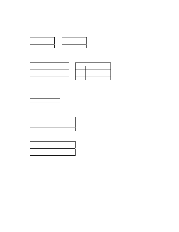
The following tables give the jack pin-outs for a fiber signal converter.
JACK
OPERATION
J1 – 25 Pin DB-F
J2 TX1
(out)
PIN OPERATION
J3
RX1 (in)
2
TX-P (out)
J4
TX2 (out)
3
RX-P (in)
J5 RX2
(in)
7 GND
Loop-Back Test: To perform a loop-back, for testing purposes only, connect the following using
a fiber optic cable jumper.
J2 & J3 or J4 & J5
TX to RX
Serial Cable (W-1249)
This table lists the pin connections when using a serial cable (W-1249).
DB9-F DB25-F
Pin 3 – TX
Pin 2 – TX
Pin 2 – RX
Pin 3 – RX
Pin 5 – GND
Pin 7 - GND
Serial Adaptor (A-1603)
DB9-F DB25-M
Pin 3 – TX
Pin 2 – TX
Pin 2 – RX
Pin 3 – RX
Pin 5 – GND
Pin 7 - GND
Appendix A: Signal Converter
A-2