Modem, Fiber optic, Signal termination between two (or more) signs – Daktronics AF-3065-34-RGB User Manual
Page 24: Rs422 interconnection, Modem -8, Fiber optic -8, Signal termination between two (or more) signs -8, Rs422 interconnection -8
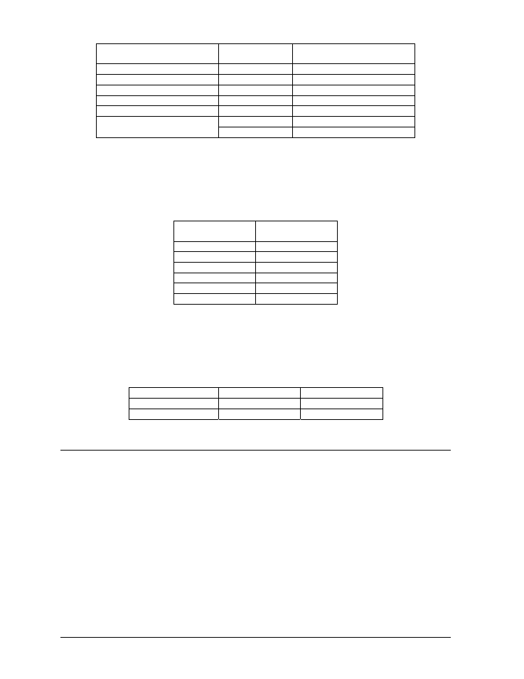
Signal Converter (J4/J5)
Field Cabling
Terminal Block TB2 (RS422
In)
Pin 1 (GND)
Red
Pin 1 (GND)
Pin 2 (RX-P)
Black
Pin 2 (TX-P)
Pin 3 (RX-N)
Brown
Pin 3 (TX-N)
Pin 4 (TX-P)
White
Pin 4 (RX-P)
Pin 5 (TX-N)
Blue
Pin 5 (RX-N)
Green
Pin 6 (GND)
Pin 6 (GND)
Bare (Shield)
N.C.
Modem
In a display that uses a modem, Signal In routes first to a telecommunications connector and
terminated per the table below. A 6-conductor phone cord with RJ11 connectors (part number 0A-
1137-0160) relays the signal to the modem (refer to Drawing A-125900). A second phone cord
(0A-1137-0160) transfers the data from the modem to J1 (RS232 IN) on the controller.
Terminal Block
TB31
Function
Pin 1
Pin 2
Pin 3
TIP-P
Pin 4
Ring-P
Pin 5
Pin 6
Fiber Optic
When fiber optic cables are used, signal from the converter enters the fiber board (J4/J5). An
adapter module (Daktronics part number 0A-1146-0029) allows the use of a 6-conductor phone
cord with RJ11 connectors (part number 0A-1137-0160) to relay the signal to J1 (RS232 IN) on
the controller.
Signal Converter
Field Cabling
Sign A Data In
J2 (TX1)
J5 (RX2)
J3 (RX1)
J4 (TX2)
3.8 Signal Termination Between Two (or More) Signs
Reference Drawings:
System Riser Diagram, RS232.............................................................. Drawing A-96058
System Riser Diagram, RS422.............................................................. Drawing A-92681
System
Riser
Diagram, Modem............................................................. Drawing A-88426
System Riser Diagram, Fiber .............................................................. Drawing A-110559
Schematic; Fiber/Modem Input............................................................ Drawing A-125900
Signal
Input, Venus 1500 .................................................................... Drawing A-129110
RS422 Interconnection
This is the most common method of terminating signal between two or more displays. A 6-
conductor cable is used and one end terminates at the “RS422 OUT” 6-position terminal block
(TB3) on the first display. The other end terminates at the “RS422 IN” 6-position terminal block
(TB2) in the second display.
Electrical Installation
3-8