Component identification, Component identification -4, Figure 2: controller -4 – Daktronics AF-3065-34-RGB User Manual
Page 10
sided stand-alone displays. They can become double-faced by mounting them back-to-back with a
second unit.
The Venus 1500 controller is a software package that runs under Windows 98, ME or NT
â
4.0 or 2000
operating systems on an IBM
â
-compatible computer. Refer to the Venus 1500 controller operator’s
manual for installation and operation of the Venus 1500 controller editing station.
Refer to Sections 4.2 and 4.3 for the summaries of how signal and power are routed through the
displays.
1.5 Component
Identification
The following illustrations depict some of the more commonly accessed Galaxy display components.
Because Daktronics occasionally alters standard design to meet customer needs, the actual display
design may very slightly from the illustrations below.
This is only a brief overview. Refer to Section 4 for additional information on maintaining the
various display components.
Com Port: A COM port is a connector on the back of the control computer. The COM port is used to
control the display network through either a 9- or a 25-pin serial connector.
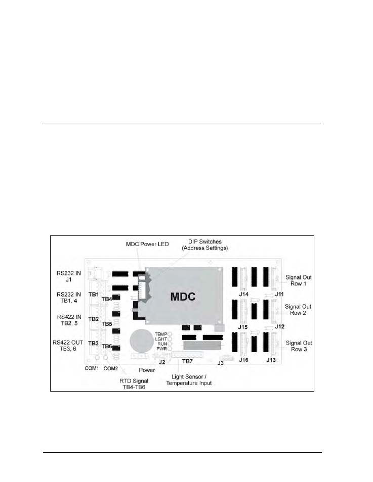
Controller: The display’s controller is the “brains” of the display (refer to Figure 2). The controller
receives signal information from the control computer, translates it, and activates the appropriate
pixels on the display accordingly.
Figure 2: Controller
Galaxy
ä: Daktronics trademarked name for LED monochrome, tri-colored or RGB matrix displays.
Network: A network consists of multiple displays connected to each other. Up to 240 displays can
exist on one network.
Introduction
1-4