Modules & drivers, Modules & drivers -4 – Daktronics AF-3065-34-RGB User Manual
Page 30
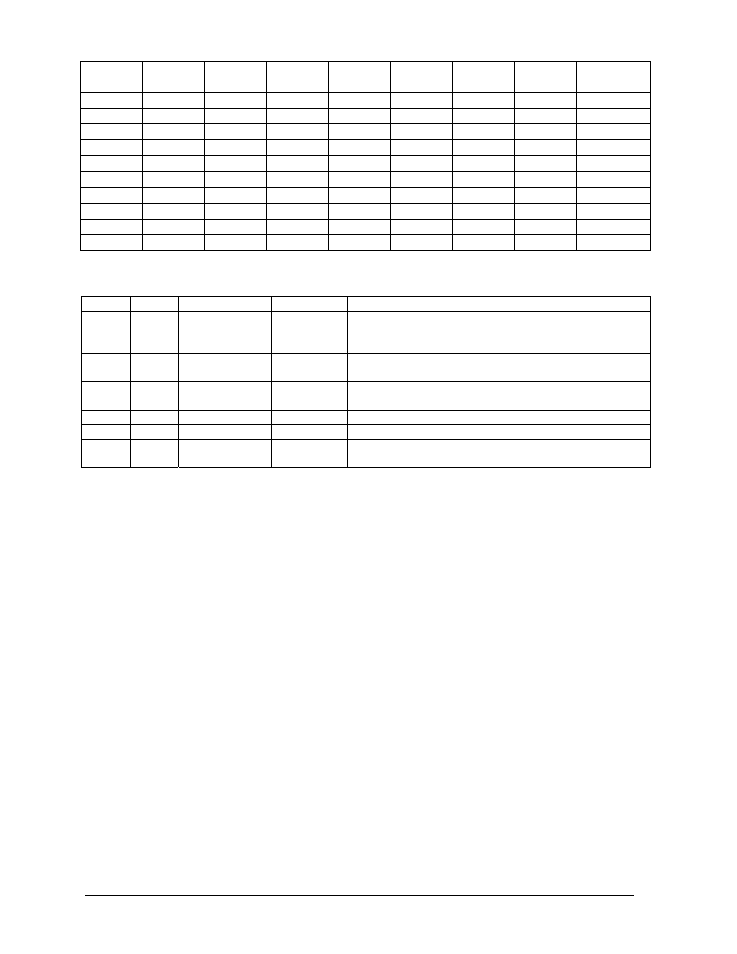
Switch
8
Switch
7
Switch
6
Switch
5
Switch
4
Switch
3
Switch
2
Switch
1
Address
Off Off Off Off Off Off Off Off
Test Mode
Off Off Off Off Off Off Off On 1
Off Off Off Off Off Off On Off 2
Off Off Off Off Off Off On On 3
Off Off Off Off Off On Off Off 4
Off Off Off Off Off On Off On 5
Off Off Off Off Off On On Off 6
Off Off Off Off Off On On On 7
… … … … … … … … …
On On On On Off Off Off Off 240
Four diagnostic LEDs are located on the controller; the table below tells what each LED denotes.
LED Color
Function
Operation
Summary
TEMP Red
Temperature
Level
Flashes
Flash rate is dependent upon the temperature.
Flashes faster in high temperature and slows as the
temperature decreases.
LGHT Red Photocell
Light
Level
Flashes
Flash rate is dependent on the light level. Flashes
faster in bright light and slows as darkness descends.
RUN Red Controller
Steady
Flash
A steady flash indicates the controller is running
correctly. Normal flash rate is about once a second.
PWR
Green
Power
Always On
Power to the data input circuit when lit.
RX1
Yellow Com 1
Flashes
Turns on and flashes when receiving information.
RX2
Yellow Com 2
Flashes
Turns on and flashes when receiving information,
typically used in custom applications.
The controller contains two jumpers (W1 and W2) for use with a modem system. The jumpers
must jump both pins for a modem system.
Complete the following steps to remove the controller from the display.
1. Disconnect power from J2.
2. Remove all power and signal connections from the board. “Locked” connectors are released
by squeezing together the tabs, then carefully pulling them from the jack. When replacing the
board, it is helpful to have the cables labeled as to which was removed from which connector.
3. Remove each of the six nuts holding the board in place.
4. Follow the previous steps in reverse order to install a new controller board.
Modules & Drivers
The module and driver board are a single functional unit. The LED power supplies are identified
as assemblies (refer to Power Supplies, following in this section). Each power supply unit
controls four modules; a power supply assembly (two power supply units) controls eight.
To remove a module, complete the following steps:
1. Locate the latch access fasteners on the module. One is centered below the top row of pixels
and one is centered above the bottom row.
2. With a
c²Allen wrench, turn the latch access fasteners a quarter turn as seen in Figure 22.
The top one should be turned clockwise and the bottom one counter-clockwise.
3. Pull the display module far enough to reach around the back and disconnect the ribbon cables.
Maintenance &
4-4
Troubleshooting