Main disconnect, Signal termination from computer to display, Rs232 – Daktronics AF-3065-34-RGB User Manual
Page 23: Rs422, Main disconnect -7, Signal termination from computer to display -7, Rs232 -7, Rs422 -7
2. Route the power cables through the power conduit in the rear of the sign and to the enclosure.
3. Connect the white neutral wire to neutral bus.
4. If one power line is being terminated (120VAC), connect the black “hot” wire to L1. Install
jumper per Drawing A-154965.
5. If two power lines are being terminated (120/240VAC). Connect the second “hot” wire to L2.
6. Connect the green grounding wire to the grounding bus L1. Refer to Figure 19.
Main Disconnect
The National Electrical Code requires the use of a lockable power disconnect near the display.
Provide a lockable disconnect switch (knife switch) at the display location so that all power lines
can be completely disconnected. Use a 3-conductor disconnect so that both hot lines and the
neutral can all be disconnected. The main disconnect should be mounted at or near the point of
power supply connection to the display. A main disconnect is to be provided for each supply
circuit to the display.
The disconnecting means must be located in a direct line of sight from the display or outline
lighting that it controls. This requirement provides protection by enabling a worker to keep the
disconnecting means within view while working on the display.
Exception: Disconnecting means that are capable of being locked in the open position may be
located elsewhere.
3.7
Signal Termination from Computer to Display
Reference Drawings:
System Riser Diagram, Modem ............................................................. Drawing A-88426
System Riser Diagram, RS422.............................................................. Drawing A-92681
System Riser Diagram, RS232.............................................................. Drawing A-96058
System Riser Diagram Fiber................................................................ Drawing A-110559
Schematic; Fiber/Modem Input............................................................ Drawing A-125900
Signal
Input, Venus 1500 .................................................................... Drawing A-129110
RS232
One end of the signal cable should terminate to the 6-position terminal block on the controller
labeled “RS232 IN” (TB1). Drawing A-129110 shows the terminal block wiring. The opposite
end terminates at the J-box near the display. The controlling computer connects to the J-box
through the serial cable (refer to Drawing A-96058).
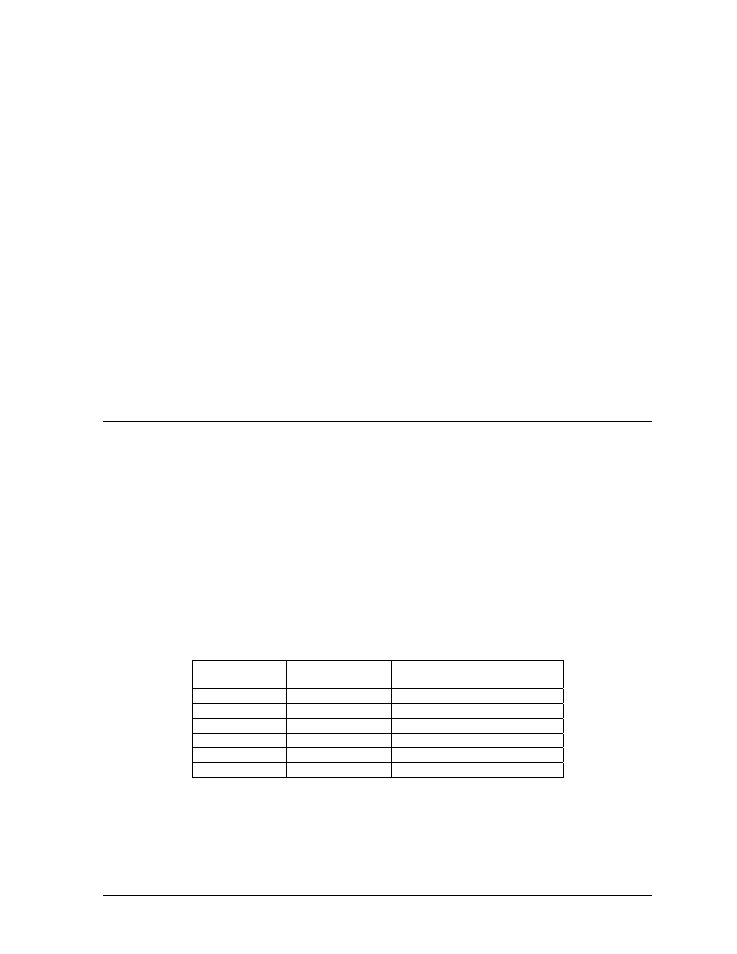
J-Box
Field Cabling
Terminal Block TB1 (RS232
In)
Pin 1 (RTS)
Pin 2 (GND)
Pin 2 (RX-P)
Clear
Pin 3 (TX-P)
Pin 3 (GND)
Shield
Pin 4 (GND)
Pin 1 (TX-P)
Black
Pin 5 (RX-P)
Pin 6 (DCD)
RS422
One end of the signal cable should terminate to the 6-position terminal block in the display labeled
“RS422 IN” (TB2). Drawing A-129110 shows the terminal block wiring. The opposite end is
terminated at the signal converter (Daktronics part number 0A-1127-0237) in the control room.
Electrical Installation
3-7