Ventilation requirements, Lifting the display, Display mounting – Daktronics AF-3065-34-RGB User Manual
Page 14: Ventilation requirements -2, Lifting the display -2, Display mounting -2
2.3 Ventilation
Requirements
Reference Drawings:
Shop
Drawing;
AF-3065-8-32 High...................................................... Drawing B-148418
Shop Drawing; AF-3065-40-48 High.................................................... Drawing B-148419
Fans are mounted in the bottom of the display and to the back sheet for ventilation. Maintain a
minimum distance of 3
² (7.62cm) below the display to maintain proper airflow. Refer to the
appropriate shop drawing for additional information.
If the display cabinet is completely enclosed:
·
6 square inches of unobstructed opening per module must be provided to ensure adequate
cooling.
·
Allowances must be made to compensate for the percentage of material covering the openings
in the structure.
·
For adequate cooling, forced ventilation may be required. If air is forced into the enclosed
cabinet, 10 cubic feet per minute must be provided per module (10.6
² x 10.6² active area).
If these requirements are not met, the Galaxy display warranty may be void.
2.4
Lifting the Display
The top of the larger displays is equipped with eyebolts that are used to lift the unit. Take special care
to ensure that the rated load of the eyebolts is not exceeded. Refer to the information at the end of this
section labeled Eyebolts to determine the allowable load of the eyebolts shipped with the display.
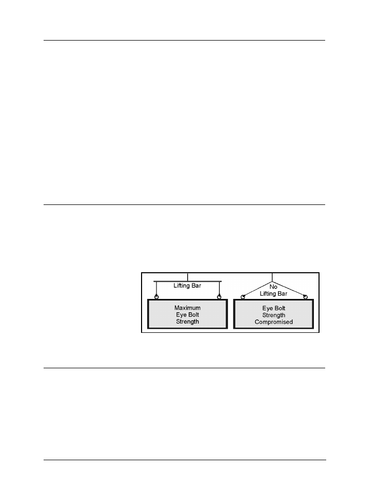
Figure 8 illustrates both the correct (left example) and the incorrect (right example) method of lifting
a display. Lift the display as shown on the left, with the lifting bar. Use every lifting point provided!
Do not attempt to permanently
support the display by the
eyebolts.
Figure 8: Lifting the Display (Correct, Left; Incorrect, Right)
If removing the eyebolts,
adequately seal the holes using
½-13 bolts and sealing washers
and silicone along the threads.
This ensures that water does
not enter the display.
2.5 Display
Mounting
Reference Drawings:
Mtg Clip Angles; AX-XXXX-40/48XX-34B............................................ Drawing A-128799
Mtg Clip Angles AX-XXX-8/32XX-34B................................................. Drawing A-128801
Shop
Drawing;
AF-3065-8-32 High...................................................... Drawing B-148418
Shop Drawing; AF-3065-40-48 High.................................................... Drawing B-148419
The method used to mount displays can vary greatly from location to location. For this reason, only
general mounting topics can be addressed in this manual.
Mechanical Installation
2-2