Fiber interconnection, Fiber interconnection -9 – Daktronics AF-3065-34-RGB User Manual
Page 25
Display A
Data Out (TB3)
Field Cabling
Display B
Data In (TB2)
Pin 1 (GND)
Green
Pin 6 (GND)
Pin 2 (Data TX-N)
Blue
Pin 5 (Data RX-N)
Pin 3 (Data TX-P)
White
Pin 4 (Data RX-P)
Pin 4 (Data RX-N)
Brown
Pin 3 (Data TX-N)
Pin 5 (Data RX-P)
Black
Pin 2 (Data TX-P)
Pin 6 (GND)
Red
Pin 1 (GND)
Pin 6 (GND)
Bare (Shield)
N.C.
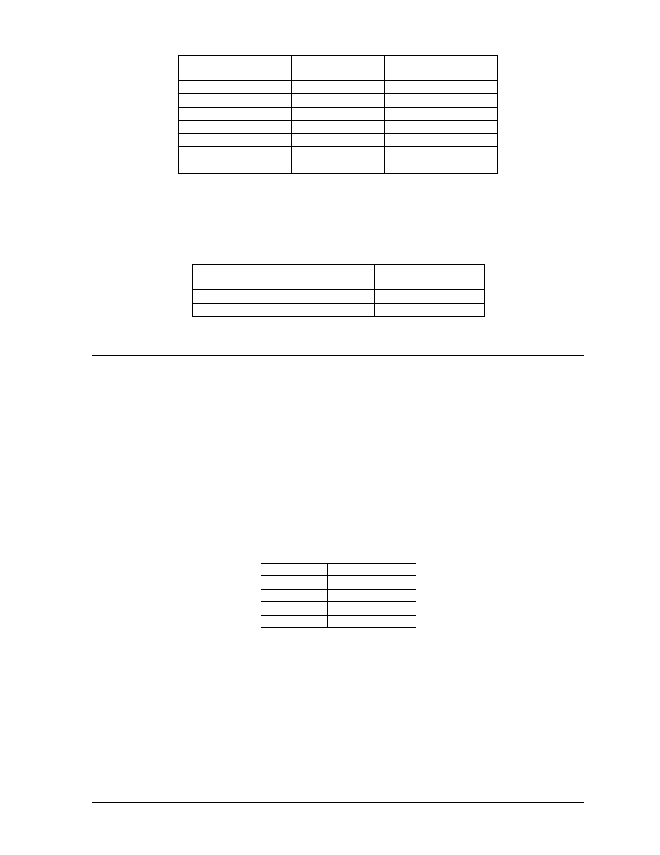
Fiber Interconnection
A four-conductor fiber cable is used in connecting two or more displays in the Fiber
Interconnection method. Connect the fiber cable to the fiber cards of the display as described in
Drawing A-125900 and on the following table.
Display A
Data Out (J2 & J3)
Field
Cabling
Display B
Data In (J4 & J5)
J2 (TX1)
J5 (RX2)
J3 (RX1)
J4 (TX2)
3.9
Optional Temperature Sensor Electrical Installation
Reference Drawings:
Temp
Sensor Mounting ......................................................................... Drawing A-79767
Signal
Input, Venus 1500 .................................................................... Drawing A-129110
After mounting the optional temp sensor as described in Section 2.6, Optional Temperature Sensor
Mounting, follow these steps to complete the electrical installation. A 2-pair, individually shielded
cable (Belden 5594, Daktronics part number W-1234) is used to connect the sensor to the controller.
1. Run ½
² conduit from the sensor location to the controller within the display. The cable must be
routed through one-foot of ½
² metal conduit that should be earth-grounded to protect the sensor
and controller from lightning damage.
2. Connect the cable to the temperature sensor terminal block within the temperature sensor as
follows:
Wire Color
Terminal Block
Red V+
Green P
Black GND
White N
*Note: Do not terminate shield at this point.
3. Install the mesh screen with the four screws enclosed.
4. Disconnect power to the display before attaching the cable.
5. Connect the cable to the temperature sensor terminal block on the controller (TB7) per the
following table:
Electrical Installation
3-9