Section 2: mechanical installation, 1 lifting the scoreboard, Section 2 – Daktronics WP-2101 Water Polo LED Scoreboard User Manual
Page 9: Mechanical installation, Lifting the scoreboard
Mechanical Installation
3
Section 2:
Mechanical Installation
For indoor scoreboards, mechanical installation typically consists of lifting and permanently
mounting the scoreboard to a wall. The mechanical specification drawings listed in Appendix A show
the recommended number and spacing of wall anchors for indoor scoreboard models.
For outdoor scoreboards, mechanical installation typically consists of installing concrete footing and
steel beams and mounting the scoreboard to the beams. Two beams are required, set 4'-6" (1.4 m)
apart, center-to-center. The columns, footings, and all connection details must be designed and
certified by a professional engineer licensed to practice in the state of the scoreboard installation.
Be sure that the installation complies with local building codes.
Note: Daktronics does not assume any liability for any installation derived from the information
provided in this manual or installations designed and installed by others.
2.1 Lifting the Scoreboard
Most Daktronics scoreboards are shipped equipped with at least one
1
/
2
" eyebolt for lifting,
as well as pre-drilled holes along the top and bottom of each cabinet for wall attachment.
Eyebolts are located along the top of the cabinet for each scoreboard or scoreboard section.
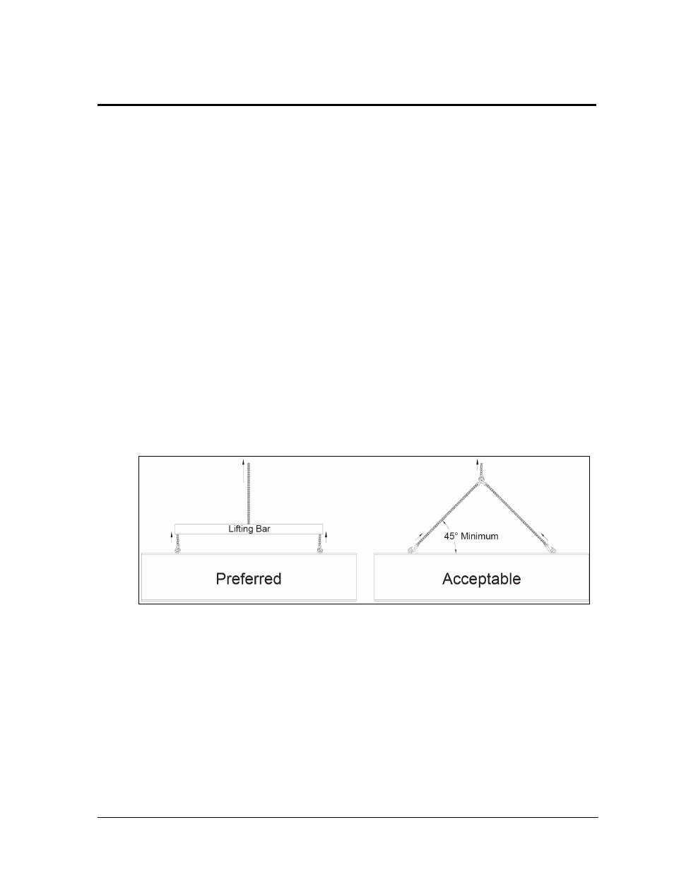
Daktronics strongly recommends using a spreader bar, or lifting bar, to lift the display.
Spreader bars ensure the force on the eyebolts remains straight up, minimizing lifting stress.
Figure 4 illustrates the preferred scoreboard lifting method on the left and an acceptable
alternative lifting method on the right. When lifting the display:
Use a spreader bar if possible.
Use every lifting point provided.
Cables and chains attached to the eyebolts and directly to a center lifting point, as shown in
the right-hand example in Figure 4, can create a dangerous lateral force on the eyebolts and
may cause the eyebolts to fail. The smaller the angle between the cable and the top of the
display, the lighter the sign must be to safely lift it. If this method must be used, ensure a
minimum angle between the chain and scoreboard of at least 45°.
Do NOT attempt to lift the display if the angle is less than 45°.
Figure 4: Lifting Methods