4 power-on self-test (post), Radio settings, 5 indoor signal connection – Daktronics WP-2101 Water Polo LED Scoreboard User Manual
Page 18: Power-on self-test (post), Indoor signal connection
12
Electrical Installation
3.4 Power-On Self-Test (POST)
The scoreboard performs a self-test each time that power is turned on and the control console
is powered off or not attached to the scoreboard. If the control console is attached and
powered on, the self-test does not run, and data from the control console is displayed on the
scoreboard after a brief period of time. Each scoreboard self-test pattern will vary depending
on the scoreboard model, the number of drivers and types of digits. Figure 13 shows an
example of the LED bar test pattern that each digit performs.
Radio Settings
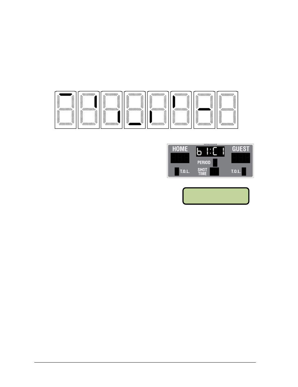
If a radio receiver is installed (see Section 4.5), the
radio broadcast settings (“b1”) and the channel
settings (“C1”) will be displayed in the clock digits
during the POST (Figure 14). These values must
match the settings in the control console (refer to
Figure 15 and the appropriate control console
manual listed in Section 1.1).
3.5 Indoor Signal Connection
Signal installation (for systems without radio control) requires routing control cable from the
scoreboard control console to a signal junction box (J-box) near the display. Refer to Drawing
A-28124 and Drawing A-125316 in Appendix A for signal wire connection.
1. Route signal cable in conduit from the scoreboard location to the control location.
At a minimum, use paired, 22 AWG shielded cable (part # W-1077).
2. Install a J-box at the scoreboard location and connect a
1
/
4
" phone plug (part #
0L-40683) to the cable. Be sure to connect the cable shielding only in this J-box.
3. Insert the plug into the SIGNAL IN jack, located on the left side of the scoreboard.
Note: Refer to Drawing A-1166920 if the signal jack is not already installed.
4. Install a dual
1
/
4
" J-box at the control location. Separate Main and Auxiliary
scoreboard jacks on the J-box allow operation of several displays with one controller,
as well as control of individual boards with multiple controllers.
5. Connect a signal cable from the dual
1
/
4
" J-box to the J1, J2, or J3 jack on the back of
the All Sport 5000 console or J2/J3 on the OmniSport 2000 console.
If using a Main Clock Start/Stop Switch (part # 0A-1166-0003), connect it to the
J4 jack on the All Sport 5000 console or J8 jack on the OmniSport 2000 console.
If using a Shot Clock Start/Stop Switch (part # 0A-1196-0031), connect it to the J7
jack on the All Sport 5000 console or J9 jack on the OmniSport 2000 console.
Figure 13: Digit Segment POST
Figure 14: Radio Settings in Clock Digits
Figure 15: Radio Settings (Console)
RADI O SETTI NGS
BCAST 1 CHAN 01