Connection – Daktronics WP-2101 Water Polo LED Scoreboard User Manual
Page 17
Electrical Installation
11
Connect the grounding electrode cable at the local disconnect, never at the display
driver/power enclosure.
Use a disconnect that opens all of the ungrounded phase conductors.
Connection
Both power and signal cables are routed into the scoreboard from the rear via conduit.
All power and signal wiring terminates at the load center. Note that systems with radio
control do not require external signal wiring.
Refer to the component location drawings listed in Appendix A to locate the front access
panel to the load center enclosure. Remove the screws to open the access panel. Remove the
metal cover of the load center to expose the components (Figure 12).
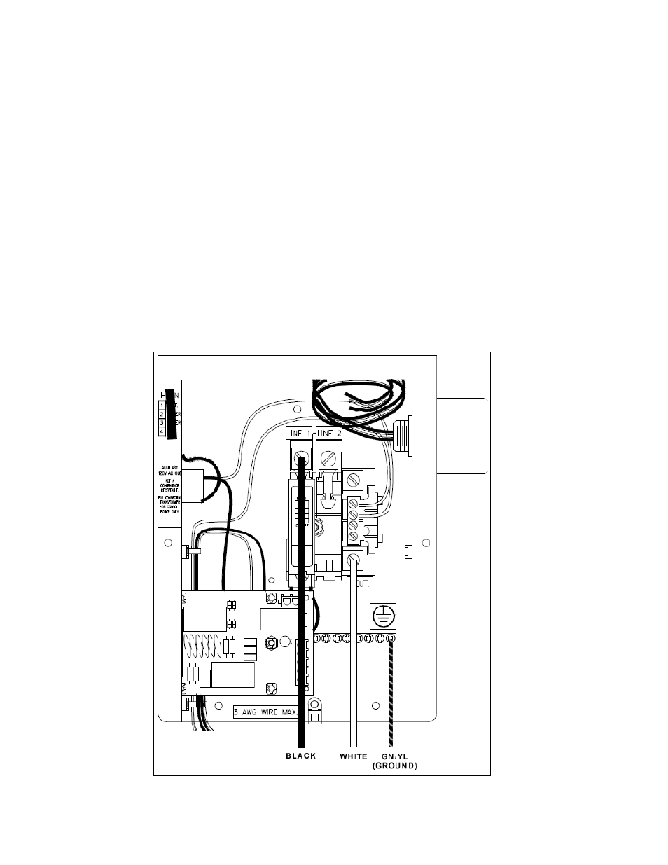
Connect the appropriate wires coming through the rear of the scoreboard to the load center
terminals, as described below and shown in Figure 12.
live wire (black) to LINE 1
neutral (white) wire to NEUT.
ground wire (green/yellow) to the grounding buss bar
Figure 12: Load Center Power Connections (Cover Removed)