6 outdoor signal connection, 7 power/signal interconnect, Outdoor signal connection – Daktronics WP-2101 Water Polo LED Scoreboard User Manual
Page 19: Power/signal interconnect
Electrical Installation
13
3.6 Outdoor Signal Connection
1. Route signal cable in conduit from the
control location into the knockout on
the rear of the scoreboard. At a
minimum, use a paired, 22 AWG
shielded cable (part # W-1077).
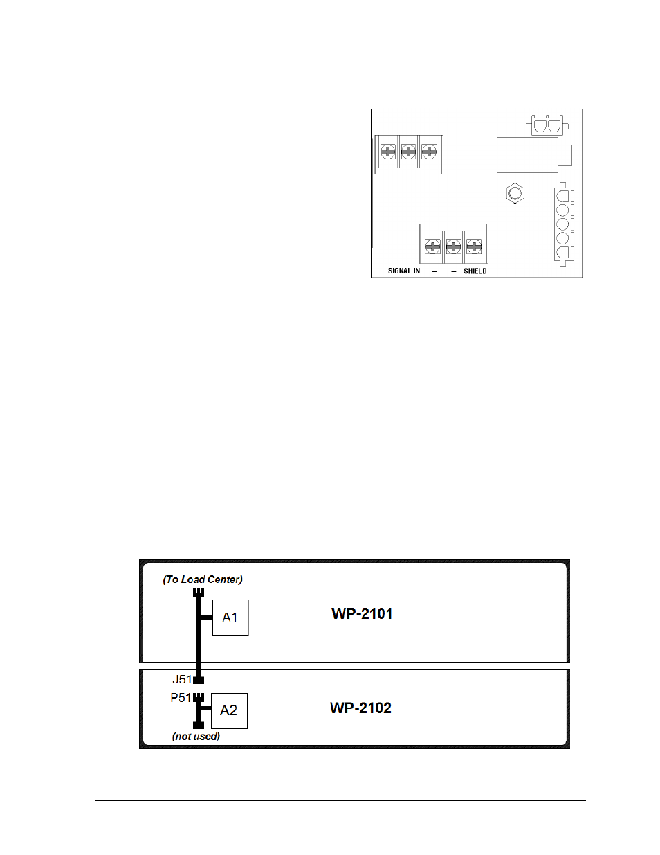
2. Connect red signal wire to positive (+)
and black signal wire to negative (–) at
the SIGNAL IN terminal block of the
signal surge arrestor card (Figure 16),
located in the lower-left corner of the
load center enclosure (Figure 12).
Note: Be sure to properly connect the
shield (silver) wire to the SHIELD terminal.
3. Install an indoor or outdoor
1
/
4
" J-box as needed at the control location.
4. Connect a signal cable from the
1
/
4
" J-box to the J1, J2, or J3 jack on the back of the All
Sport 5000 console or J2/J3 on the OmniSport 2000 console.
If using a Main Clock Start/Stop Switch (part # 0A-1166-0003), connect it to the
J4 jack on the All Sport 5000 console or J8 jack on the OmniSport 2000 console.
If using a Shot Clock Start/Stop Switch (part # 0A-1196-0031), connect it to the J7
jack on the All Sport 5000 console or J9 jack on the OmniSport 2000 console.
3.7 Power/Signal Interconnect
The WP-2102 has no power cord or signal jacks. Instead, both power and signal are received
via an interconnect harness to the WP-2101. Route the plug labeled P51 through the hole in
the bottom of the WP-2101 cabinet down into the hole in the top of the WP-2102 cabinet and
connect to the mating jack labeled J51. Refer to Figure 17.
Figure 16: Signal Surge Arrestor Card
Figure 17: Power/Signal Connection, WP-2102