Radio interference, 6 segmentation & digit designation, 7 schematics – Daktronics WP-2101 Water Polo LED Scoreboard User Manual
Page 28: Segmentation & digit designation, Schematics
22
Scoreboard Troubleshooting
Radio Interference
If it has been determined that a nearby scoreboard’s radio signal is interfering, the settings of
the wireless radio receiver inside the scoreboard(s) must be changed.
1. To locate the radio receiver, simply look for the
black antenna sticking out the front of the
scoreboard. Component location drawings also
show the exact position where the radio receiver
will be mounted.
2. Open the access panel to which the receiver is
attached as described in Section 4.2.
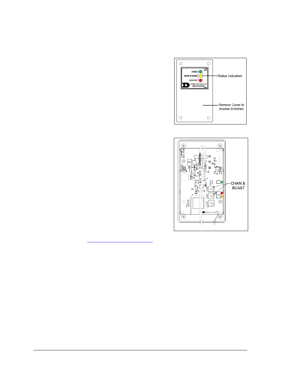
3. The radio receiver has a plastic cover with a
window to view status indicators (Figure 23).
Note: While it is necessary for the scoreboard to
be powered on to check the indicators, always
disconnect scoreboard power before servicing.
4. Remove the four screws in each corner using a
#2 Philips screwdriver and lift off the cover.
5. Use a small flathead screwdriver to set the
CHAN and BCAST switches to a new channel
and broadcast group (1-8) as needed (Figure 24).
Be sure to always leave FUNC set to “1”.
6. Screw the cover back on and securely close the
access panel.
7. Enter the correct sport code and new radio
settings into the console to test the radio control
(refer to Figure 15 and the appropriate control
console manual listed in Section 1.1).
For more information, refer to the Gen VI Radio
Installation Manual (DD2362277), available
online a
4.6 Segmentation & Digit Designation
In each digit, certain LEDs always go on and off together. These groupings of LEDs are called
segments. Drawing A-38532 in Appendix A details which connector pin is wired to each
digit segment and the wiring color code used throughout the display.
The component location drawings in Appendix A specify the driver connectors controlling
the digits. Numbers shown in hexagons in the upper half of each digit indicate which
connector is wired to that digit.
4.7 Schematics
For advanced scoreboard troubleshooting and repair, it may be necessary to consult the
schematic drawings. Located in Appendix A, schematic drawings show detailed power and
signal wiring diagrams of internal display components such as drivers, horns, and
transformers as well as optional components like radio receivers.
Figure 23: Radio Receiver w/ Cover
Figure 24: Radio Receiver Switches