4 led drivers, Untitled – Daktronics Single Section DistaView Outdoor LED Scoreboards Generation IV User Manual
Page 39
5-4
Scoreboard
Maintenance
and Troubleshooting
Drawing A-285892 is the schematic diagram for the 8-column driver and Drawing
A-286657 and A-704861 is the schematic diagram for the 16-column driver used in Daktronics
outdoor DistaView scoreboards. Drawing A-229706 shows the schematic diagram
for multi-driver displays. The schematics include power and signal inputs and all
wiring for the models described in this manual.
5.4 LED Drivers
In the scoreboard, the LED drivers perform the task of switching digits on and off.
Refer to Drawings A-178197 and A-178235. Each driver has up to19 connectors
providing power and signal inputs to the circuit and outputs to the digits and
indicators. The connectors function as follows:
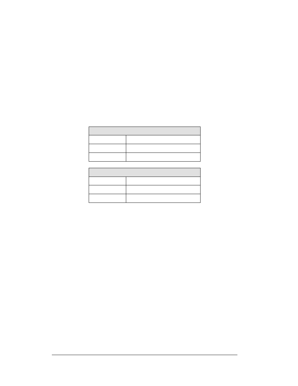
8-Column LED Driver
Connector No.
Function
1 – 8
Output to digits and indicators
17 Controls
power/signal
16-Column LED Driver
Connector No.
Function
1 – 16
Output to digits and indicators
17 Controls
power/signal
Output connectors 1 through 16 each have nine pins. Pin 7 provides power (hot) to
the digit or indicators wired to that connector. The other eight pins provide switching
connections.
For the scoreboard to receive signal and function properly, the driver must be set to
the correct address. This address is set with jumper wires in a 12-pin plug which
mates with a jack on the driver.
Address settings can be configured by using the SI dip switch. See Drawing A-
290261 for more information.