5 scoreboard mounting – Daktronics Single Section DistaView Outdoor LED Scoreboards Generation IV User Manual
Page 27
3-4 Mechanical
Installation
Each display has plastic plugs in the rear for power and signal entrance. Refer to
Drawings A-55007, A-61904, A-113568, A-127287, A-149074, A-152777,
A-173484, A-176286, A-179304, A-206385, A-206433, A-206437, A-222869, A-
222872 and A-222875 for locations. Power and signal are brought into the INNING
section (housing the master driver) through these external plastic plugs.
Refer to the installation specifications drawings listed above for further details
regarding scoreboard installation.
Drawings A-206433 and A-222872 detail scoreboard installation including one ad
panel and Drawings A-206437 and A-222875 detail installation including two ad
panels. Refer to those drawings for detailed information regarding installing your
scoreboard with ad panels.
These scoreboard models use an inverted channel mounting, illustrated in Drawing
A-55101. Refer to any installation specifications drawing (listed in Appendix: A)
for your model to determine the center-to-center distance of the poles.
3.5 Scoreboard Mounting
There are two basic styles for mounting Daktronics single-section outdoor
scoreboards. Installation procedures are detailed later in this section. Use the
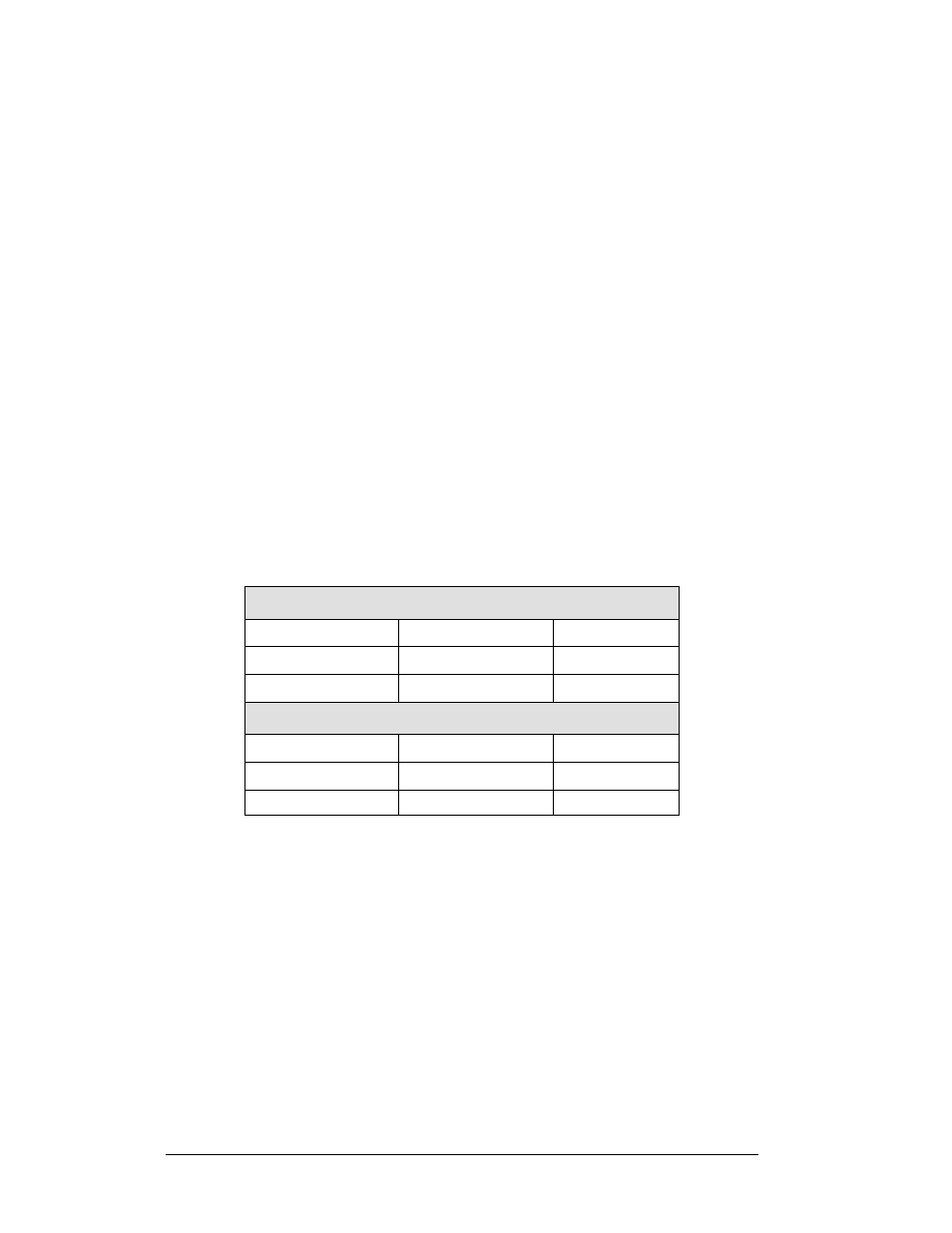
following tables to determine the mounting method required for your scoreboard:
Method 1
BA-624-31
BA-2010-31
SO-2008-31
BA-1018-31
FB-824-31
SO-2013-31
BA-2004-31
MS-2004-31
Method 2
BA-2515-31
BA-2718-31
MS-3918-31
BA-2618-31
FB-4005-31
SO-2918-31/32
BA-2715-31
MS-915-31
TI-2015-31