6 mounting method 1 – Daktronics Single Section DistaView Outdoor LED Scoreboards Generation IV User Manual
Page 28
3.6 Mounting Method 1
Reference Drawings:
Display Mounting ........................................................... Drawing A-44412
Ad Panel Mounting ......................................................... Drawing A-52187
Drawing A-44412 shows the hardware used for mounting the scoreboard to the
beams. Mounting hardware includes inner and outer mounting clamps, clip angles,
1
/
2
-13 x 15" threaded rods,
3
/
8
-16 x 2" bolts, hex nuts and split lockwashers, and
1
/
2
"
square nuts, hex nuts, and split lockwashers. Each section of the scoreboard attaches
at the top and the bottom to all the beams. The drawing also shows top and side
views of the scoreboard secured to the beams.
Note: The threaded rods do not pass through the flanges of the beams, but instead
run along both sides of each beam.
Refer to the installation specifications drawing for your scoreboard model (listed in
Section 3.4) to determine the center-to-center distance of the poles for each model.
Review the illustration of the mounting hardware in Drawing A-44412, or refer to
Figure 4, and then use the following procedure for each section.
1. Using
3
/
8
" bolts, loosely attach the inner and outer mounting clamps to the
rear flanges of the scoreboard horizontal frame members. Measure the beam
spacing and position the clamps to fit on either side of the beams.
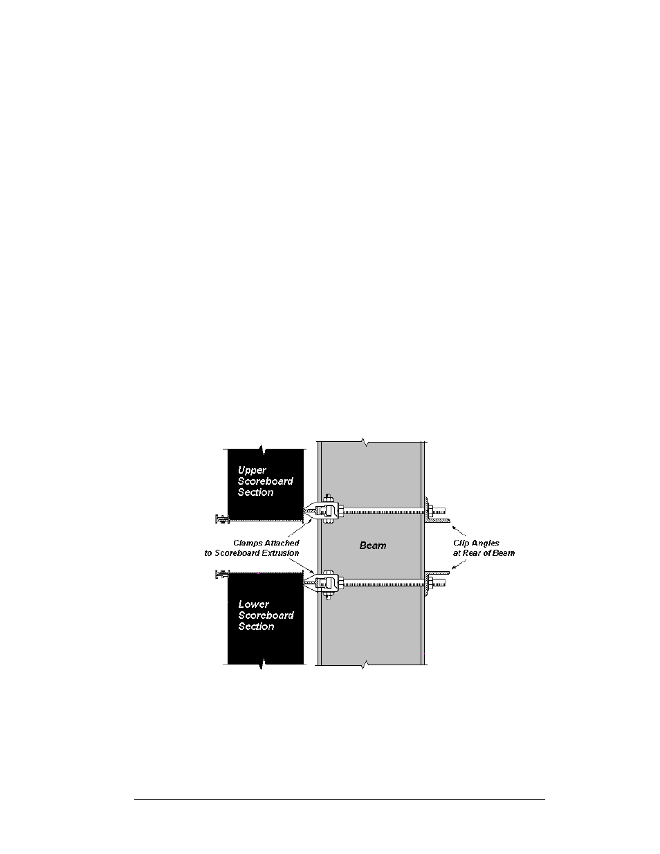
Figure 4: Clamp Mounting Method, Side View
2. Insert a
1
/
2
" square nut into each mounting clamp. Screw a threaded rod into
each of the nuts from the rear.
3. Position the scoreboard at the front of the beams with the threaded rods
extending from the rear of the clamps, straddling the beams. Raise the
scoreboard section to the desired height.
Mechanical Installation
3-5