Replacing a driver, 3 schematic – Daktronics Single Section DistaView Outdoor LED Scoreboards Generation IV User Manual
Page 38
6. Close and secure the digit panel
and test the scoreboard.
Replacing a Driver
Drivers are typically mounted inside the scoreboard and immediately behind a digit,
but location and mounting varies with the model of the scoreboard. Refer to the
component locations drawings in Section 5.2 for the location of your scoreboard
driver. All scoreboards in this manual are front-accessible.
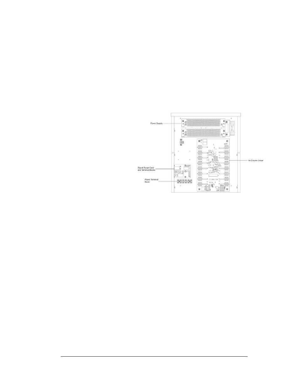
Figure 8: 16-column driver enclosure
Each driver is enclosed
with a transformer and
signal terminal block.
Before a failed driver
can be reached, the
enclosure must be
accessed. Follow these
steps:
1. Open the digit
panel or
scoreboard
face panel as
described in
the previous
sections.
2. Remove the
cover from the
driver enclosure.
3. Disconnect all connectors from the driver. Release each connector by
squeezing together the locking tabs as you pull the connector free.
Note: When reconnecting, remember that these are keyed connectors and
will attach in one way only. Do not attempt to force the connections.
4. Remove the screws, nuts, or wing nuts securing the driver to the inside of
the enclosure.
5. Carefully lift the driver from the display and place it on a clean, flat surface.
6. Follow steps 1 through 5 in reverse order to attach a new driver.
5.3 Schematic
Reference Drawings:
Schematic; DistaView OD LED Multi-driver Display .... Drawing A-229706
Schematic; XFMR 8 Col, GEN IV, DistaView LED ...... Drawing A-285892
Schematic; XFMR 16 Col, GEN IV, DistaView LED .... Drawing A-286657
Schematic; XFMR 16 Col, GEN IV, Outdoor Driver ... Drawing A-704861
Scoreboard Maintenance
5-3
and Troubleshooting