Power supplies, Removing/changing a power supply – Daktronics BA-1518 Generation IV Multi-Section Outdoor LED Scoreboard User Manual
Page 84
Module latches must be fully engaged to create a watertight seal around the edge of the
module. The module should be firmly seated against the display when the latches are
fully engaged.
Each module assembly contains a module housing (containing LEDs and the driver board) and a
louver assembly. Drawings B-126111 and B-126112 illustrate the various module components.
Individual components such as louvers can be removed for service, but Daktronics recommends
that the module be kept intact and that the entire assembly be sent in for repair or replacement.
The module and driver are a single functional unit. Each module assembly is made up of a module
housing (containing LEDs and the driver) and a louver assembly.
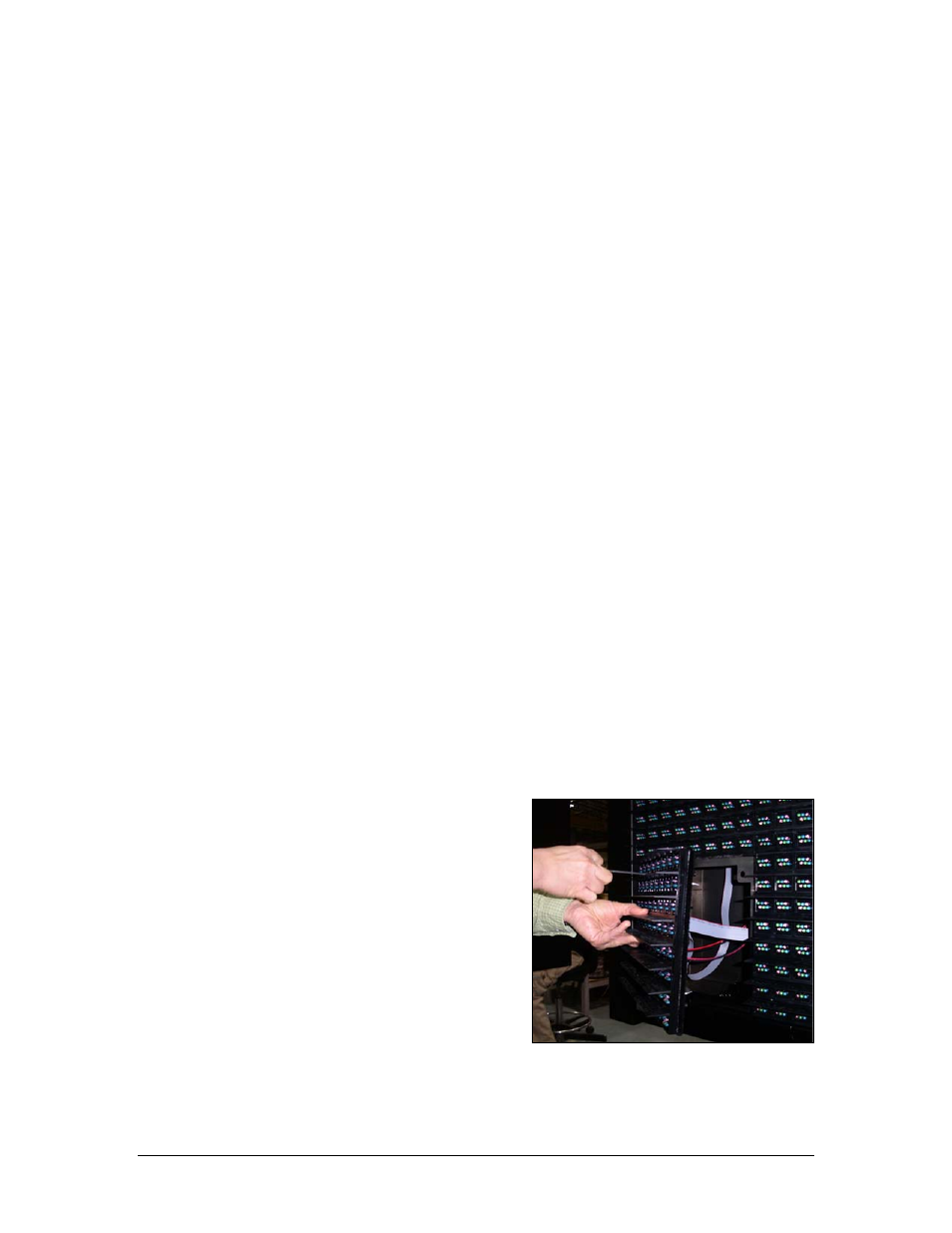
1. Locate the latch access fasteners on the module (one is centered below the second row of
pixels and one is centered above the bottom two rows)
2. With a
1
/
8
" hex wrench, turn both latch access fasteners a quarter turn counter-clockwise
to open as shown in Figure 21 – and the clockwise to close.
3. Gently pull the module far enough forward to reach behind the back and disconnect the
power and ribbon cables
When installing a module, reverse the previous steps and take note of the following points.
•
The weather-stripping on the back edge of the module must be intact and in good condition if
it is to prevent water from seeping into the display.
•
The module latches must be fully engaged to create a watertight seal around the edge of the
module. The module should be firmly seated against the display when the latches are fully
engaged.
Power Supplies
Reference Drawings:
Schematic, Amber TNMC, GEN IV ....................... Drawing A-252645
Schematic, Red TNMC, GEN IV ........................... Drawing A-252681
The red-LED TNMC uses a single power supply
assembly to power all modules in the 8x32 and
8x48 models. The amber TNMC uses a dual power
supply assembly to power all modules in the 8x32
or 8x48 models. Refer to Drawings A-252645 or
A-252681.
Figure 21: Removing a Module
Removing/Changing a Power Supply
Complete the following steps to remove a power
supply from the display:
1. See the directions in the preceding
Module and Drivers subsection for
information on how to access the
component from the front or rear.
2. Disconnect all the wires connected to the power supply.
3. Remove the hardware holding the power supply in place to free the unit.
9-8 TNMC
Maintenance
- BA-1524 Generation IV Multi-Section Outdoor LED Scoreboard BA-2006 Generation IV Multi-Section Outdoor LED Scoreboard BA-2007 Generation IV Multi-Section Outdoor LED Scoreboard BA-2012 Generation IV Multi-Section Outdoor LED Scoreboard BA-2013 Generation IV Multi-Section Outdoor LED Scoreboard BA-2020 Generation IV Multi-Section Outdoor LED Scoreboard BA-3718 Generation IV Multi-Section Outdoor LED Scoreboard BA-3724 Generation IV Multi-Section Outdoor LED Scoreboard FB-1424 Generation IV Multi-Section Outdoor LED Scoreboard FB-1430 Generation IV Multi-Section Outdoor LED Scoreboard FB-1524 Generation IV Multi-Section Outdoor LED Scoreboard FB-1530 Generation IV Multi-Section Outdoor LED Scoreboard FB-1624 Generation IV Multi-Section Outdoor LED Scoreboard FB-1630 Generation IV Multi-Section Outdoor LED Scoreboard FB-1630L Generation IV Multi-Section Outdoor LED Scoreboard FB-1730 Generation IV Multi-Section Outdoor LED Scoreboard FB-1830 Generation IV Multi-Section Outdoor LED Scoreboard MS-2020 Generation IV Multi-Section Outdoor LED Scoreboard MS-2009 Generation IV Multi-Section Outdoor LED Scoreboard SO-1830L Generation IV Multi-Section Outdoor LED Scoreboard SO-2011 Generation IV Multi-Section Outdoor LED Scoreboard SO-1930 Generation IV Multi-Section Outdoor LED Scoreboard FB-2007 Generation IV Multi-Section Outdoor LED Scoreboard SO-1830 Generation IV Multi-Section Outdoor LED Scoreboard FB-2004 Generation IV Multi-Section Outdoor LED Scoreboard SO-1624 Generation IV Multi-Section Outdoor LED Scoreboard FB-2003 Generation IV Multi-Section Outdoor LED Scoreboard SO-1424 Generation IV Multi-Section Outdoor LED Scoreboard FB-2002 Generation IV Multi-Section Outdoor LED Scoreboard FB-2001 Generation IV Multi-Section Outdoor LED Scoreboard MS-2918 Generation IV Multi-Section Outdoor LED Scoreboard SO-2030 Generation IV Multi-Section Outdoor LED Scoreboard FB-1830L Generation IV Multi-Section Outdoor LED Scoreboard MS-2118 Generation IV Multi-Section Outdoor LED Scoreboard SO-2014 Generation IV Multi-Section Outdoor LED Scoreboard