Fiber optic – Daktronics BA-1518 Generation IV Multi-Section Outdoor LED Scoreboard User Manual
Page 62
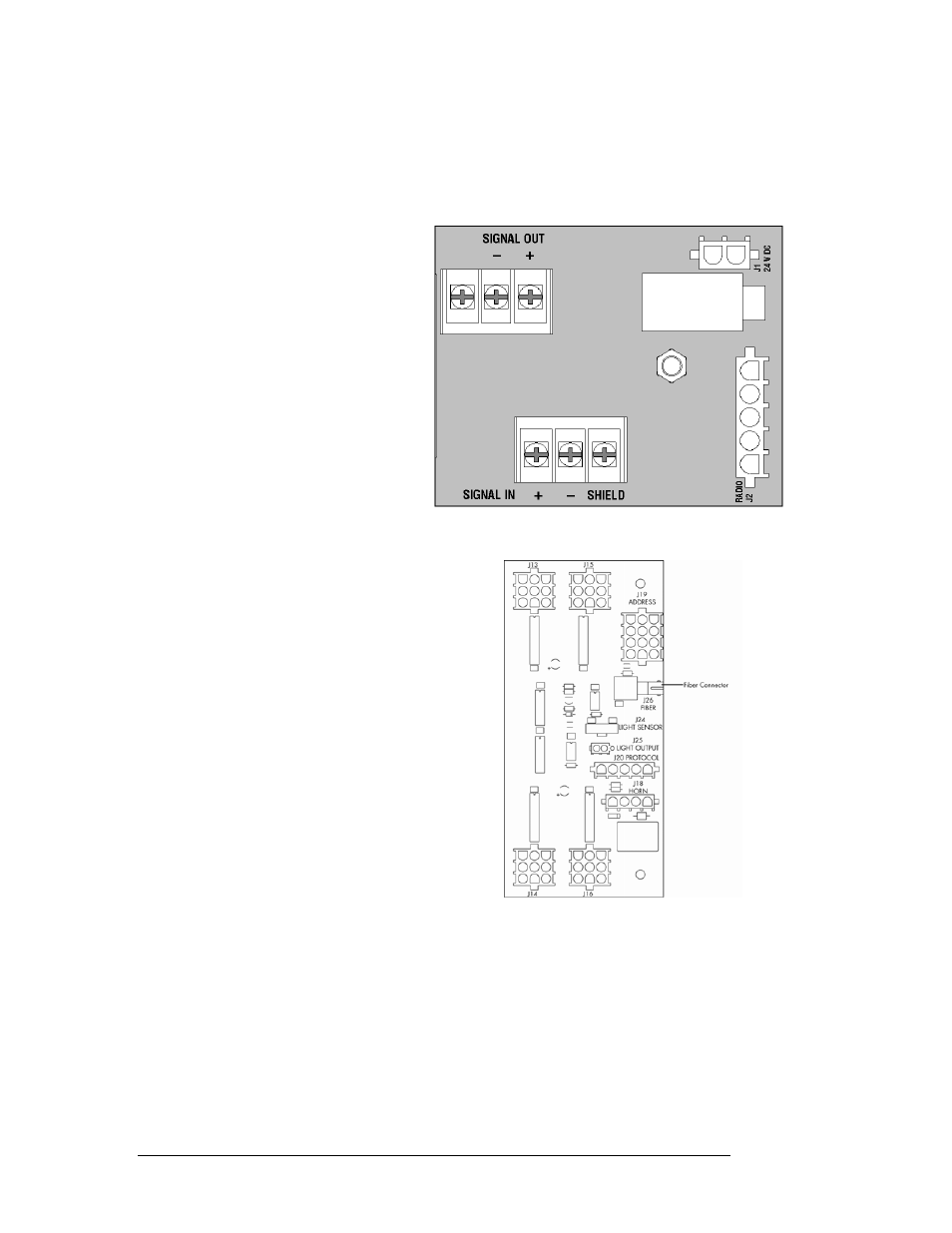
Route signal cabling to the signal surge arrestor card in the upper left corner of the
driver enclosure. The connections are labeled to permit easy installation. At the
Signal In terminal block on the PCB, connect the red signal wire to the positive
terminal, the black to the negative terminal, and the shield (silver) wire to the shield
terminal.
Note: It is important that the shield
wire is properly connected to the
shield terminal on the signal surge
arrestor card.
Figure 7: Signal Surge Arrestor Card
Figure 7 (on the previous page)
illustrates the printed circuit board
and the terminal blocks.
For signal cable, Daktronics
recommends, as a minimum,
single-pair, shielded cable, 22
AWG (Daktronics part number W-
1077). Two-pair shielded cable
(Daktronics part W-1614) is
preferred.
Figure 8: Driver Fiber Connection Location
Fiber Optic
Another common signal communication
method is using fiber optic cabling. A
minimum cabling of multi-mode; 62.5/125
um; and 2-core fiber cable is recommended.
(Daktronics part number is W-1242.) See
Figure 8 for the location of fiber connector on
the LED driver. (See Drawing A-288137 for
the complete image of the LED driver.)
For additional information on signal
connection, refer to the All Sport 5000 Series
control console operation manual ED-11976.
7-4 Electrical
Installation
- BA-1524 Generation IV Multi-Section Outdoor LED Scoreboard BA-2006 Generation IV Multi-Section Outdoor LED Scoreboard BA-2007 Generation IV Multi-Section Outdoor LED Scoreboard BA-2012 Generation IV Multi-Section Outdoor LED Scoreboard BA-2013 Generation IV Multi-Section Outdoor LED Scoreboard BA-2020 Generation IV Multi-Section Outdoor LED Scoreboard BA-3718 Generation IV Multi-Section Outdoor LED Scoreboard BA-3724 Generation IV Multi-Section Outdoor LED Scoreboard FB-1424 Generation IV Multi-Section Outdoor LED Scoreboard FB-1430 Generation IV Multi-Section Outdoor LED Scoreboard FB-1524 Generation IV Multi-Section Outdoor LED Scoreboard FB-1530 Generation IV Multi-Section Outdoor LED Scoreboard FB-1624 Generation IV Multi-Section Outdoor LED Scoreboard FB-1630 Generation IV Multi-Section Outdoor LED Scoreboard FB-1630L Generation IV Multi-Section Outdoor LED Scoreboard FB-1730 Generation IV Multi-Section Outdoor LED Scoreboard FB-1830 Generation IV Multi-Section Outdoor LED Scoreboard MS-2020 Generation IV Multi-Section Outdoor LED Scoreboard MS-2009 Generation IV Multi-Section Outdoor LED Scoreboard SO-1830L Generation IV Multi-Section Outdoor LED Scoreboard SO-2011 Generation IV Multi-Section Outdoor LED Scoreboard SO-1930 Generation IV Multi-Section Outdoor LED Scoreboard FB-2007 Generation IV Multi-Section Outdoor LED Scoreboard SO-1830 Generation IV Multi-Section Outdoor LED Scoreboard FB-2004 Generation IV Multi-Section Outdoor LED Scoreboard SO-1624 Generation IV Multi-Section Outdoor LED Scoreboard FB-2003 Generation IV Multi-Section Outdoor LED Scoreboard SO-1424 Generation IV Multi-Section Outdoor LED Scoreboard FB-2002 Generation IV Multi-Section Outdoor LED Scoreboard FB-2001 Generation IV Multi-Section Outdoor LED Scoreboard MS-2918 Generation IV Multi-Section Outdoor LED Scoreboard SO-2030 Generation IV Multi-Section Outdoor LED Scoreboard FB-1830L Generation IV Multi-Section Outdoor LED Scoreboard MS-2118 Generation IV Multi-Section Outdoor LED Scoreboard SO-2014 Generation IV Multi-Section Outdoor LED Scoreboard