Daktronics BA-1518 Generation IV Multi-Section Outdoor LED Scoreboard User Manual
Page 82
Reference Drawings:
Exploded Front View; Single Panel Module .......... Drawing B-126111
Exploded Rear View; Single Panel Module ........... Drawing B-126112
Component Locations; 832/848
Red/Amb
LED, TNMC, G4 .............................. Drawing A-257029
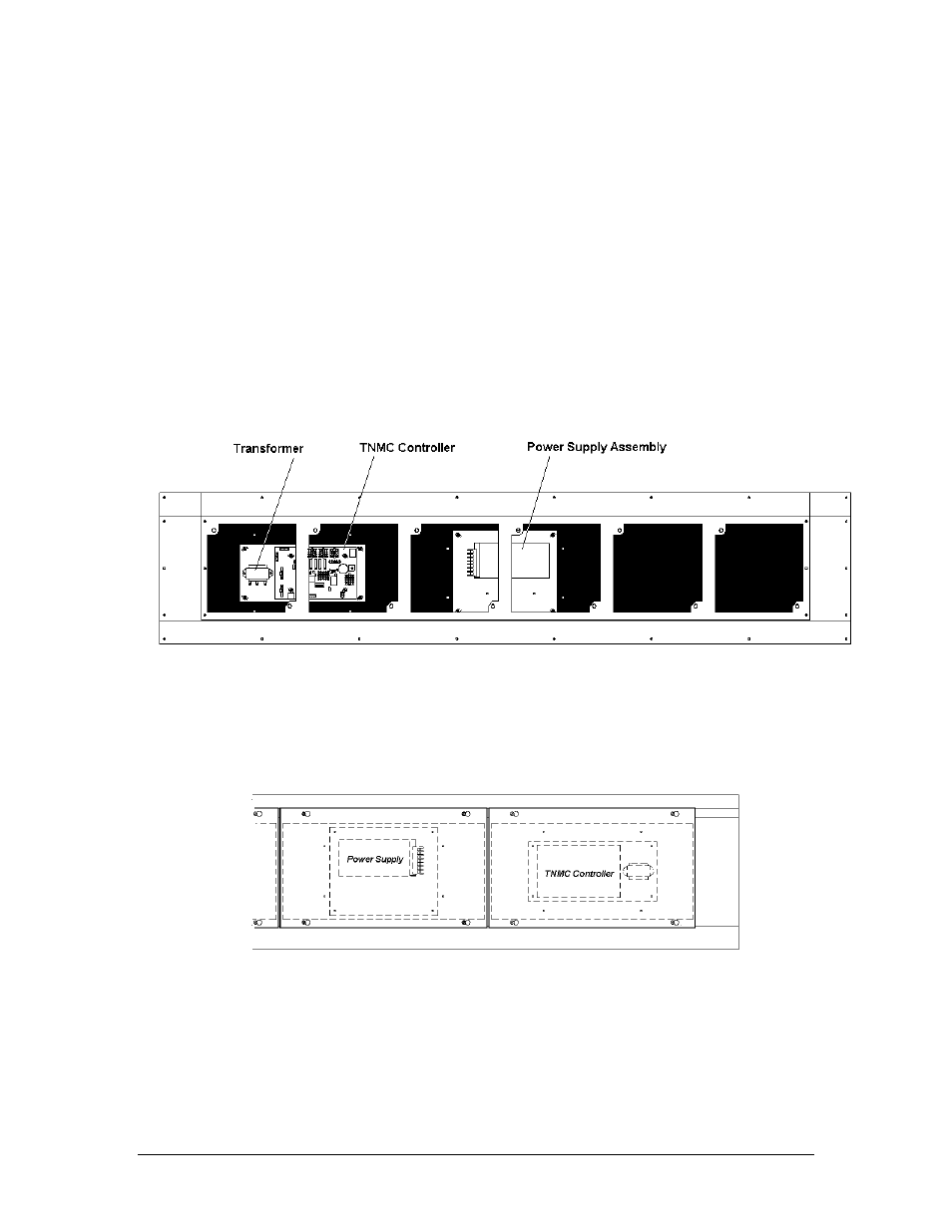
Drawing A-257029 indicates the location of the TNMC controller for each of the TNMC models.
Figure 18 below illustrates a typical TNMC layout. Complete the following steps to remove the
controller from the display.
1. To access the controller from the front, unlatch the latch fasteners on the front face the
LED module. Refer to Drawings B-126111 and B-126112. (The fasteners are referred to
as “latch plugs” on the drawings). One latch fastener is centered below the top row of
pixels and one is centered above the bottom row. They may be slightly hidden by the
louvers.
Figure 18: TNMC Internal Components (Modules Removed)
2. Using a
7
/
32
" nut driver, turn each fastener a quarter-turn. Turn the top latch clockwise
and the bottom latch counterclockwise. Carefully remove the module and detach the
ribbon cables. It may be helpful to label the cables so you will know which cable goes to
which connector when reattaching.
Figure 19: TNMC Rear Access
Note: To access the controller from the rear of the TNMC, as shown in Figure 19 (on
previous page), remove the appropriate rear-access panel from the TNMC by loosening
all four of the screws. Slide the access panel sideways to the larger part of the keyhole
and carefully lift it off the TNMC. Take care not to drop the panel, and remember that the
module controller is attached to the panel.
3. Disconnect power from J17
9-6 TNMC
Maintenance
- BA-1524 Generation IV Multi-Section Outdoor LED Scoreboard BA-2006 Generation IV Multi-Section Outdoor LED Scoreboard BA-2007 Generation IV Multi-Section Outdoor LED Scoreboard BA-2012 Generation IV Multi-Section Outdoor LED Scoreboard BA-2013 Generation IV Multi-Section Outdoor LED Scoreboard BA-2020 Generation IV Multi-Section Outdoor LED Scoreboard BA-3718 Generation IV Multi-Section Outdoor LED Scoreboard BA-3724 Generation IV Multi-Section Outdoor LED Scoreboard FB-1424 Generation IV Multi-Section Outdoor LED Scoreboard FB-1430 Generation IV Multi-Section Outdoor LED Scoreboard FB-1524 Generation IV Multi-Section Outdoor LED Scoreboard FB-1530 Generation IV Multi-Section Outdoor LED Scoreboard FB-1624 Generation IV Multi-Section Outdoor LED Scoreboard FB-1630 Generation IV Multi-Section Outdoor LED Scoreboard FB-1630L Generation IV Multi-Section Outdoor LED Scoreboard FB-1730 Generation IV Multi-Section Outdoor LED Scoreboard FB-1830 Generation IV Multi-Section Outdoor LED Scoreboard MS-2020 Generation IV Multi-Section Outdoor LED Scoreboard MS-2009 Generation IV Multi-Section Outdoor LED Scoreboard SO-1830L Generation IV Multi-Section Outdoor LED Scoreboard SO-2011 Generation IV Multi-Section Outdoor LED Scoreboard SO-1930 Generation IV Multi-Section Outdoor LED Scoreboard FB-2007 Generation IV Multi-Section Outdoor LED Scoreboard SO-1830 Generation IV Multi-Section Outdoor LED Scoreboard FB-2004 Generation IV Multi-Section Outdoor LED Scoreboard SO-1624 Generation IV Multi-Section Outdoor LED Scoreboard FB-2003 Generation IV Multi-Section Outdoor LED Scoreboard SO-1424 Generation IV Multi-Section Outdoor LED Scoreboard FB-2002 Generation IV Multi-Section Outdoor LED Scoreboard FB-2001 Generation IV Multi-Section Outdoor LED Scoreboard MS-2918 Generation IV Multi-Section Outdoor LED Scoreboard SO-2030 Generation IV Multi-Section Outdoor LED Scoreboard FB-1830L Generation IV Multi-Section Outdoor LED Scoreboard MS-2118 Generation IV Multi-Section Outdoor LED Scoreboard SO-2014 Generation IV Multi-Section Outdoor LED Scoreboard