2 power and signal connection – Daktronics BA-1518 Generation IV Multi-Section Outdoor LED Scoreboard User Manual
Page 61
• Connect the grounding electrode cable at the local disconnect, never at the
display driver/power enclosure.
• Use a disconnect that opens all of the ungrounded phase conductors.
7.2 Power and Signal Connection
Reference Drawings:
Schematic; Gen III
& IV
, OD LED, 3 Drvr Display ........ Drawing A-179541
Schematic; Gen III
& IV
, OD LED, 1 Drv w/TNMC ....... Drawing A-179790
Schematic; Gen III
& IV
OD LED, 3Dr w/TNMC ........... Drawing A-180081
Schematic; Gen III
& IV
, OD LED, 2 Drv ...................... Drawing A-180637
Schematic; Gen III
& IV
, OD LED,
2 Drv Multi-Sec w/TNMC ....................................... Drawing A-180688
Schematic; GEN IV Outdoor LED, 16 Col Driver ........ Drawing A-285779
Driver Enclosure Reference, GEN IV .......................... Drawing A-293354
Schematic; Baseball w/S.O.P.,
Gen IV optional TNMC .......................................... Drawing B-204725
Schematic; BA-2013 GEN III, Optional TNMC ............ Drawing B-260324
Route power and signal cables into the scoreboard
from the rear. There are two plastic plugs for
conduit connection in the back. All power and
signal wiring terminates at the driver enclosure.
Drawing A-293354 illustrates the 16-column
driver used in Daktronics outdoor LED
scoreboards.
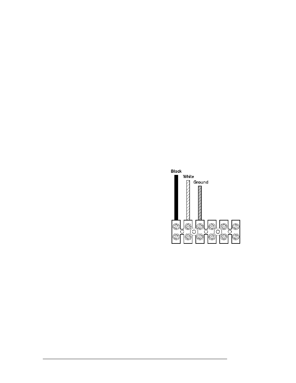
Figure 6: Power Terminal Block
To gain access to the driver enclosure, open the
access door or digit panel and remove the cover
from the enclosure. Refer to the component
locations drawings for the access location for your
scoreboard.
Connect power and signal cables at the appropriate
locations on the driver enclosure panel, shown in
Drawing A-293354.
The conventional power termination panel has been eliminated from Daktronics
outdoor scoreboards; the power feeder circuit connects directly to a terminal block in
the driver enclosure, as shown in Figure 6 above.
The terminal block is located in the lower right corner of the enclosure. Connect the
power wires as shown in the illustration. Refer to the driver engineering drawings
and the schematics listed at the beginning of this section for additional wiring details.
The schematics include a detailed illustration of the power termination.
Note: If a power receptacle is needed to operate the control console at the scoreboard
for troubleshooting, Daktronics recommends that an installation electrician provides
a 120 V outlet close to the disconnect box specifically for this purpose.
Electrical Installation
7-3
- BA-1524 Generation IV Multi-Section Outdoor LED Scoreboard BA-2006 Generation IV Multi-Section Outdoor LED Scoreboard BA-2007 Generation IV Multi-Section Outdoor LED Scoreboard BA-2012 Generation IV Multi-Section Outdoor LED Scoreboard BA-2013 Generation IV Multi-Section Outdoor LED Scoreboard BA-2020 Generation IV Multi-Section Outdoor LED Scoreboard BA-3718 Generation IV Multi-Section Outdoor LED Scoreboard BA-3724 Generation IV Multi-Section Outdoor LED Scoreboard FB-1424 Generation IV Multi-Section Outdoor LED Scoreboard FB-1430 Generation IV Multi-Section Outdoor LED Scoreboard FB-1524 Generation IV Multi-Section Outdoor LED Scoreboard FB-1530 Generation IV Multi-Section Outdoor LED Scoreboard FB-1624 Generation IV Multi-Section Outdoor LED Scoreboard FB-1630 Generation IV Multi-Section Outdoor LED Scoreboard FB-1630L Generation IV Multi-Section Outdoor LED Scoreboard FB-1730 Generation IV Multi-Section Outdoor LED Scoreboard FB-1830 Generation IV Multi-Section Outdoor LED Scoreboard MS-2020 Generation IV Multi-Section Outdoor LED Scoreboard MS-2009 Generation IV Multi-Section Outdoor LED Scoreboard SO-1830L Generation IV Multi-Section Outdoor LED Scoreboard SO-2011 Generation IV Multi-Section Outdoor LED Scoreboard SO-1930 Generation IV Multi-Section Outdoor LED Scoreboard FB-2007 Generation IV Multi-Section Outdoor LED Scoreboard SO-1830 Generation IV Multi-Section Outdoor LED Scoreboard FB-2004 Generation IV Multi-Section Outdoor LED Scoreboard SO-1624 Generation IV Multi-Section Outdoor LED Scoreboard FB-2003 Generation IV Multi-Section Outdoor LED Scoreboard SO-1424 Generation IV Multi-Section Outdoor LED Scoreboard FB-2002 Generation IV Multi-Section Outdoor LED Scoreboard FB-2001 Generation IV Multi-Section Outdoor LED Scoreboard MS-2918 Generation IV Multi-Section Outdoor LED Scoreboard SO-2030 Generation IV Multi-Section Outdoor LED Scoreboard FB-1830L Generation IV Multi-Section Outdoor LED Scoreboard MS-2118 Generation IV Multi-Section Outdoor LED Scoreboard SO-2014 Generation IV Multi-Section Outdoor LED Scoreboard