Modules and drivers – Daktronics BA-1518 Generation IV Multi-Section Outdoor LED Scoreboard User Manual
Page 83
4. Remove all power and signal connections from the board. Release “locked” connectors
by squeezing together the tabs, and then carefully pulling them from the jack. Label the
cables, indicating which cable was removed from which connector; the labeling will be
helpful when you replace the board.
5. Remove the four nuts holding the board in place.
6. Follow the previous steps in reverse order to install a new controller board.
Modules and Drivers
Reference Drawings: (for displays installed Prior to 11/29/05)
Exploded Front View; Single Panel Module .......... Drawing B-126111
Exploded Rear View; Single Panel Module ........... Drawing B-126112
The module and driver board are a single, functional unit. To remove a module, complete the
following steps:
1. The modules are attached to an internal
frame called the module mounting
panel. Find the latch-access fasteners
(referred to as “latch plugs” on the
drawings) on the front of the module.
One is centered below the top row of
pixels and one is centered above the
bottom row. (They may be slightly
hidden by the louvers.)
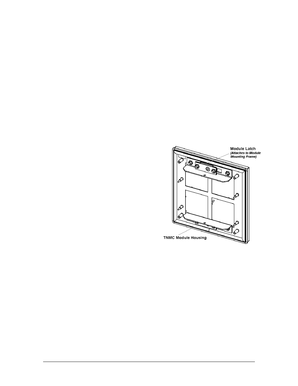
2. Unlatch the latch fasteners, illustrated in
Figure 20, by turning them a quarter-
turn using a
7
/
32
" nut driver. Turn the
top latch clockwise and the bottom latch
counterclockwise. Carefully remove the
module and detach the ribbon cables.
Label the cables, indicating which cable
was removed from which connector; the
labeling will be helpful when you replace the board.
Figure 20: TNMC Module (Rear View)
Note: If you are accessing the unit from the rear, follow this procedure: First, remove the
rear access panel (explained in preceding subsection.): While holding onto the module,
push it out and turn it in such a manner (generally a sideways, diagonal turn) that it will
fit through the frame opening; then pull the module back through the opening in the
frame. Carefully disconnect the ribbon cables. Once again, label the cables, indicating
which cable was removed from which connector; the labeling will be helpful when
reconnecting.
When installing a module, reverse the previous steps and take note of the following points:
Weatherstripping on the back edge of the module must be intact and in good condition to
prevent water from seeping into the display.
TNMC Maintenance
9-7
- BA-1524 Generation IV Multi-Section Outdoor LED Scoreboard BA-2006 Generation IV Multi-Section Outdoor LED Scoreboard BA-2007 Generation IV Multi-Section Outdoor LED Scoreboard BA-2012 Generation IV Multi-Section Outdoor LED Scoreboard BA-2013 Generation IV Multi-Section Outdoor LED Scoreboard BA-2020 Generation IV Multi-Section Outdoor LED Scoreboard BA-3718 Generation IV Multi-Section Outdoor LED Scoreboard BA-3724 Generation IV Multi-Section Outdoor LED Scoreboard FB-1424 Generation IV Multi-Section Outdoor LED Scoreboard FB-1430 Generation IV Multi-Section Outdoor LED Scoreboard FB-1524 Generation IV Multi-Section Outdoor LED Scoreboard FB-1530 Generation IV Multi-Section Outdoor LED Scoreboard FB-1624 Generation IV Multi-Section Outdoor LED Scoreboard FB-1630 Generation IV Multi-Section Outdoor LED Scoreboard FB-1630L Generation IV Multi-Section Outdoor LED Scoreboard FB-1730 Generation IV Multi-Section Outdoor LED Scoreboard FB-1830 Generation IV Multi-Section Outdoor LED Scoreboard MS-2020 Generation IV Multi-Section Outdoor LED Scoreboard MS-2009 Generation IV Multi-Section Outdoor LED Scoreboard SO-1830L Generation IV Multi-Section Outdoor LED Scoreboard SO-2011 Generation IV Multi-Section Outdoor LED Scoreboard SO-1930 Generation IV Multi-Section Outdoor LED Scoreboard FB-2007 Generation IV Multi-Section Outdoor LED Scoreboard SO-1830 Generation IV Multi-Section Outdoor LED Scoreboard FB-2004 Generation IV Multi-Section Outdoor LED Scoreboard SO-1624 Generation IV Multi-Section Outdoor LED Scoreboard FB-2003 Generation IV Multi-Section Outdoor LED Scoreboard SO-1424 Generation IV Multi-Section Outdoor LED Scoreboard FB-2002 Generation IV Multi-Section Outdoor LED Scoreboard FB-2001 Generation IV Multi-Section Outdoor LED Scoreboard MS-2918 Generation IV Multi-Section Outdoor LED Scoreboard SO-2030 Generation IV Multi-Section Outdoor LED Scoreboard FB-1830L Generation IV Multi-Section Outdoor LED Scoreboard MS-2118 Generation IV Multi-Section Outdoor LED Scoreboard SO-2014 Generation IV Multi-Section Outdoor LED Scoreboard