Section 2: mechanical installation, 1 lifting the scoreboard, Section 2 – Daktronics Outdoor LED Scoreboards Installation User Manual
Page 9: Mechanical installation, Lifting the scoreboard
Mechanical Installation
3
Section 2:
Mechanical Installation
Mechanical installation consists of installing concrete footing and steel beams and mounting the
scoreboard and accompanying ad panels to the beams. The product specification sheets listed in
Appendix A include installation specification drawings that show the recommended number of
beams and spacing between them. The drawings also indicate the size of beams required to support
the scoreboard at different heights and at various wind speeds. For Modular Football scoreboards
and Pari-Mutuel displays, refer to site-specific diagrams for proper placement and mounting method.
Any column and footing size dimensions are to assist with estimating installation costs; they are
estimates only and are not intended for actual construction purposes. Be sure that the installation
complies with local building codes and is suitable for the particular soil and wind conditions.
The columns, footings, and all connection details must be designed and certified by a professional
engineer licensed to practice in the state of the scoreboard installation.
Note: Daktronics does not assume any liability for any installation derived from the information
provided in this manual or installations designed and installed by others.
2.1 Lifting the Scoreboard
Scoreboards and scoreboard sections are shipped equipped with
1
/
2
" shoulder-type eyebolts
located along the top of the cabinet for the purpose of lifting.
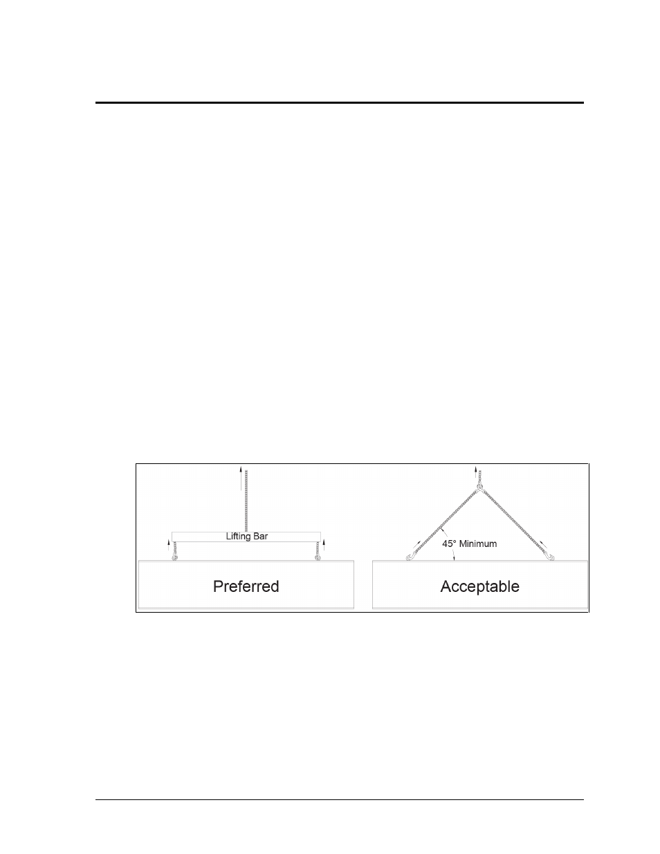
Daktronics strongly recommends using a spreader bar, or lifting bar, to lift the display.
Spreader bars ensure the force on the eyebolts remains straight up, minimizing lifting stress.
Figure 2 illustrates the preferred scoreboard lifting method on the left and an acceptable
alternative lifting method on the right. When lifting the display:
Use a spreader bar if possible.
Use every lifting point provided.
Cables and chains attached to the eyebolts and directly to a center lifting point, as shown in
the right-hand example in Figure 2, create a dangerous lateral force on the eyebolts and may
cause the eyebolts to fail. The smaller the angle between the cable and the top of the display,
the lighter the display must be to safely lift it. If this method must be used, ensure a minimum
angle between the chain and scoreboard of at least 45°.
Figure 2: Lifting Methods