2 power, Power – Daktronics Outdoor LED Scoreboards Installation User Manual
Page 20
14
Electrical Installation
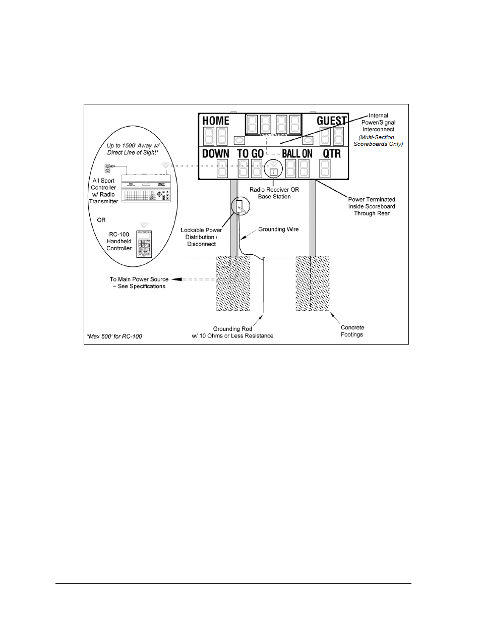
The diagram shown in Figure 14 illustrates a typical wireless setup between an outdoor
scoreboard and controller. Note that the RC-100 handheld controller and base station system
is typically only available for use with smaller single-section scoreboards and for single- or
multi-court tennis scoreboards.
For additional installation examples, such as for multi-court tennis systems, refer to the
System Riser drawings attached to the controller manual (listed in Section 1.2).
3.2 Power
Correct power installation is imperative for proper display operation. The subsections that
follow give details of display power installation. Only qualified individuals should attempt to
complete the electrical installation; untrained personnel should not attempt to install these
displays or any of the electrical components. Improper installation could result in serious
damage to the equipment or injury to personnel.
Most outdoor scoreboards require a dedicated 100-240 VAC circuit for incoming power.
Multi-court outdoor tennis scoreboards require a dedicated 120/240 VAC single phase circuit
for incoming power; a 120/208-2P circuit is also acceptable.
WARNING: It is critical that 120 V scoreboard circuits be fused at 20 A and that all
conductors used must be designed to pass a 20 A current in normal operation. For 240 V
scoreboards, consult local electrical codes. Failure to meet wiring and overcurrent
protection device requirements will void the scoreboard warranty.
Figure 14: Wireless Installation Example
(Multi-Section Scoreboards Only)